Supercharge Your Innovation With Domain-Expert AI Agents!

Improved LED (light-emitting diode) bracket production process

A technology of LED bracket and production process, which is applied in the direction of electrical components, circuits, semiconductor devices, etc., can solve the problems of difficult operation and low precision of the production process, and achieve the effects of reducing defective rate, high precision and easy installation

Inactive Publication Date: 2017-05-31
FUJIAN DINGTAI OPTOELECTRONICS TECH CO LTD
View PDF7 Cites 0 Cited by
  • Summary
  • Abstract
  • Description
  • Claims
  • Application Information

AI Technical Summary

Problems solved by technology

[0005] The invention provides an improved LED bracket production process, the main purpose of which is to overcome the defects of difficult operation and low precision of the existing LED bracket production process

Method used


Image

  • Improved LED (light-emitting diode) bracket production process
  • Improved LED (light-emitting diode) bracket production process
  • Improved LED (light-emitting diode) bracket production process

Examples


Embodiment Construction

[0025] Specific embodiments of the present invention will be described below with reference to the accompanying drawings.

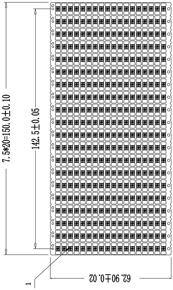
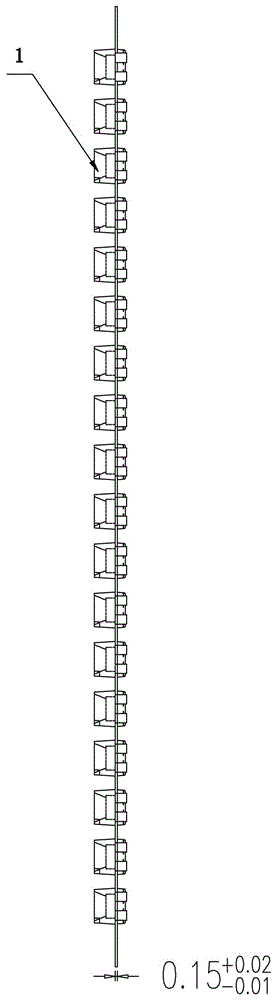
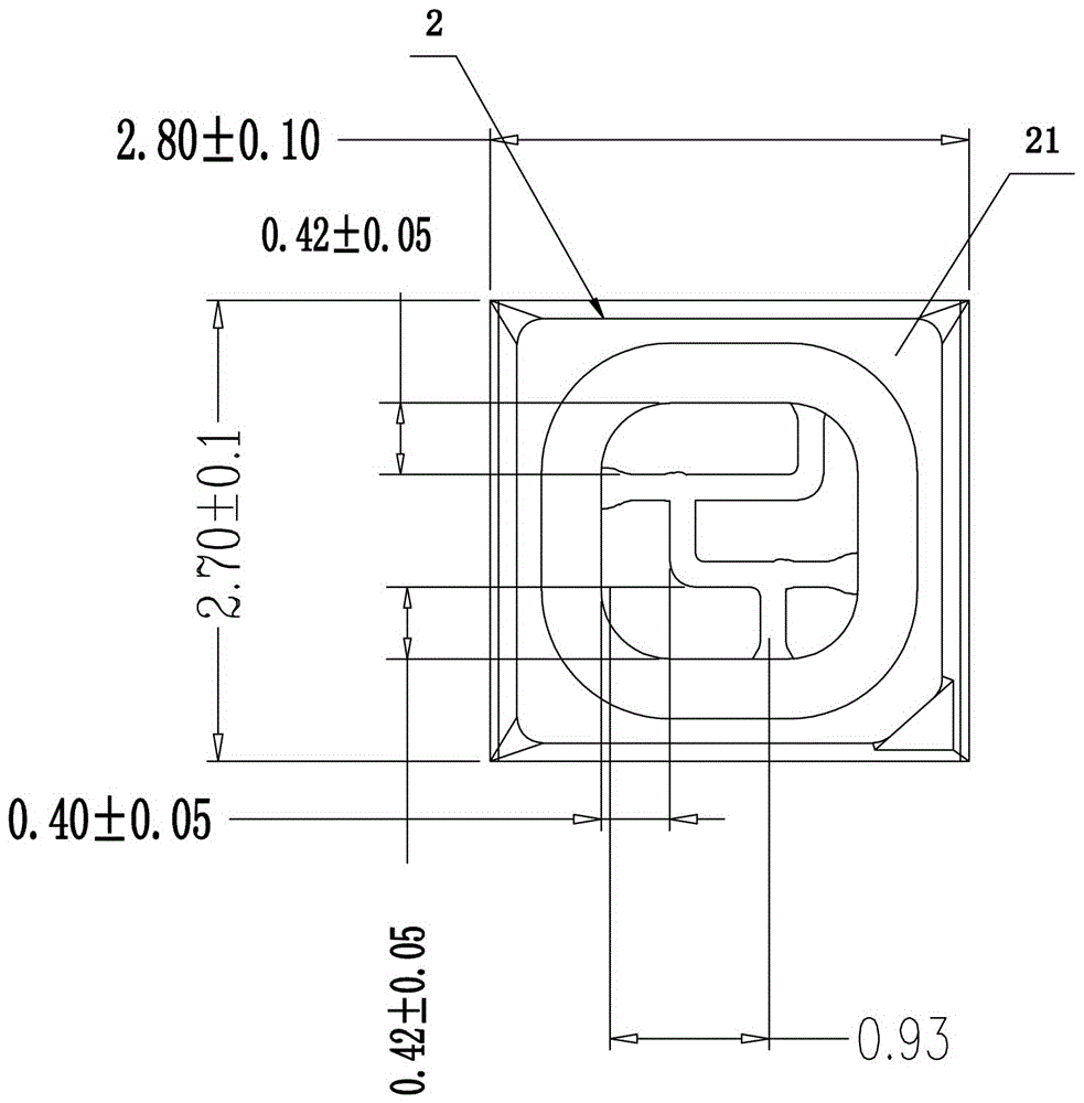
[0026] refer to figure 1 , figure 2 , image 3 and Figure 4 . An improved LED bracket production process, comprising the following steps:

[0027] step one

[0028] Put the plastic inside the 3D printer. The plastic can be EMC.

[0029] EMC-Epoxy Molding Compound is epoxy resin molding compound and epoxy molding compound. It is made of epoxy resin as matrix resin, high-performance phenolic resin as curing agent, silicon micropowder as filler, and various additives. Formed powder molding compound.

[0030] step two

[0031] Input the required model drawings of the LED bracket 1 into the computer, and then control the 3D printer through the computer to print the LED bracket 1 into shape.

[0032] step three

[0033] A layer of copper is electroplated on the outer layer of the printed LED bracket.

[0034] step four

[0035] A nickel layer is ...


PUM

PropertyMeasurementUnit
Lengthaaaaaaaaaa
Widthaaaaaaaaaa
Thicknessaaaaaaaaaa

Abstract

The invention discloses an improved LED (light-emitting diode) bracket production process. A required LED bracket model drawing is input into a computer, and then a 3D (three-dimensional) printer is controlled by the computer to print and form an LED bracket. According to the improved LED bracket production process, the LED bracket is printed by the 3D printer, and compared with the prior art, the improved LED bracket production process has the advantages that higher simplicity for operation is achieved, the accuracy of an obtained pedestal is higher, and the defect rate of a product is greatly reduced.

Description

technical field [0001] The invention relates to an LED production process, in particular to an improved LED bracket production process. Background technique [0002] The LED bracket is the bottom base of the LED lamp bead before packaging. On the basis of the LED bracket, the chip is fixed in, the positive and negative electrodes are soldered, and then packaged with packaging glue. [0003] A Chinese invention patent for an LED bracket and its production process (authorized notification number CN 102332523 B), which discloses the production process: (1) The insulating seat is obtained by injection molding; (2) The surface of the entire insulating seat is attached to the first metal by electroless plating layer; (3) laser cutting the insulating seat, etching away the metal on the laser travel route, and forming a plurality of conductive pin precursors for distinguishing positive and negative electrodes; (4) electroplating on the conductive pin precursors Deposit the second m...

Claims


Application Information

Patent Timeline
IPC IPC(8): H01L33/48H01L33/60H01L33/62
CPCH01L33/486H01L33/60H01L33/62H01L2933/0033H01L2933/0058H01L2933/0066
Inventor 黄德春袁洪峰
Owner FUJIAN DINGTAI OPTOELECTRONICS TECH CO LTD
Features
  • R&D
  • Intellectual Property
  • Life Sciences
  • Materials
  • Tech Scout
  • Unparalleled Data Quality
  • Higher Quality Content
  • 60% Fewer Hallucinations
Learn More