Switch power control method with optimized dynamic response

A technology of dynamic response and control method, applied in the direction of control/regulating system, electrical components, regulating electrical variables, etc., can solve the problems that the voltage mode cannot be directly applied to the Boost converter, the system work failure, the system setting deviation, etc., and the cost is achieved. The effect of low, high sensitivity and stable output voltage

Active Publication Date: 2017-05-31
SOUTHEAST UNIV
View PDF4 Cites 12 Cited by
  • Summary
  • Abstract
  • Description
  • Claims
  • Application Information

AI Technical Summary

Problems solved by technology

However, in practical applications, the above schemes are often subject to various restrictions. For example, the voltage mode hysteresis control cannot be directly applied to the Boost converter, and it will interact with the voltage regulation mode in the Buck converter. Mode hysteresis controllers can avoid these problems, but they are more difficult in practical applications
[0005] The above control modes need to design the control system at the beginning of the power supply design to adapt to various situations that the system may face, which often involves the derivation of the load formula. In addition, in the high-frequency switching power supply, the derivation of the formula is related to the actual work of the system. The situation often deviates, which leads to the deviation of the system settings and the failure of the system

Method used


Image

  • Switch power control method with optimized dynamic response
  • Switch power control method with optimized dynamic response
  • Switch power control method with optimized dynamic response

Examples


Embodiment Construction

[0033] The technical solution of the present invention will be described in detail below in conjunction with the accompanying drawings.

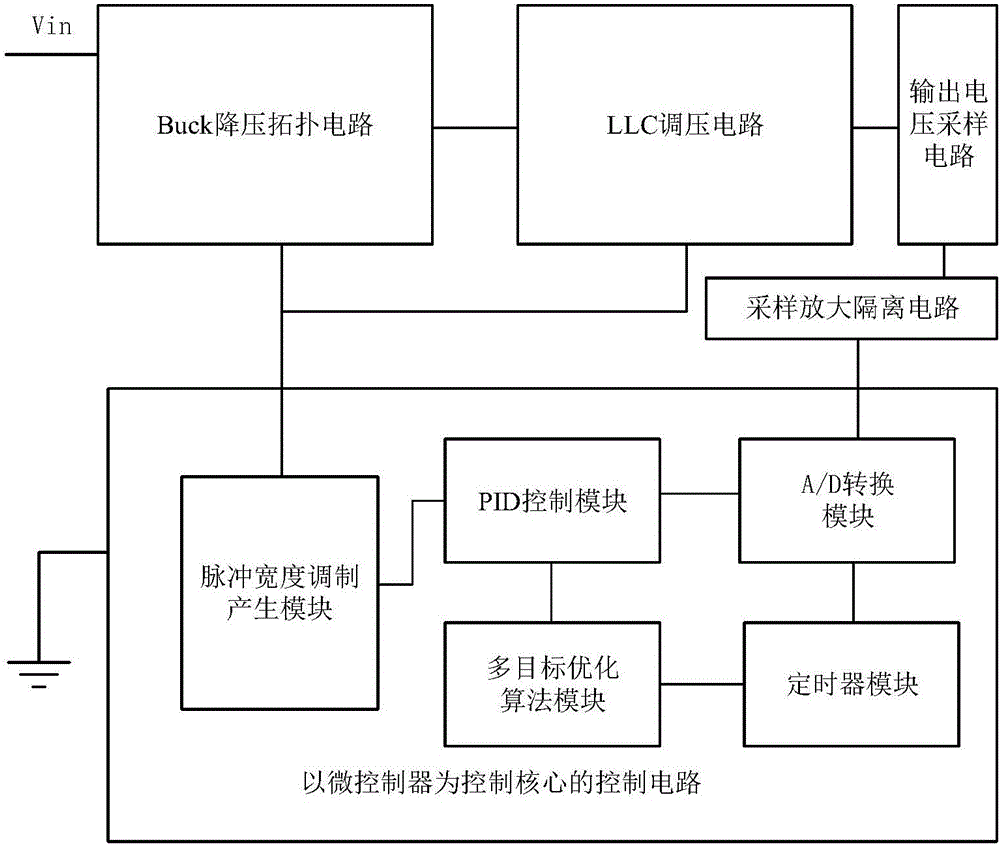
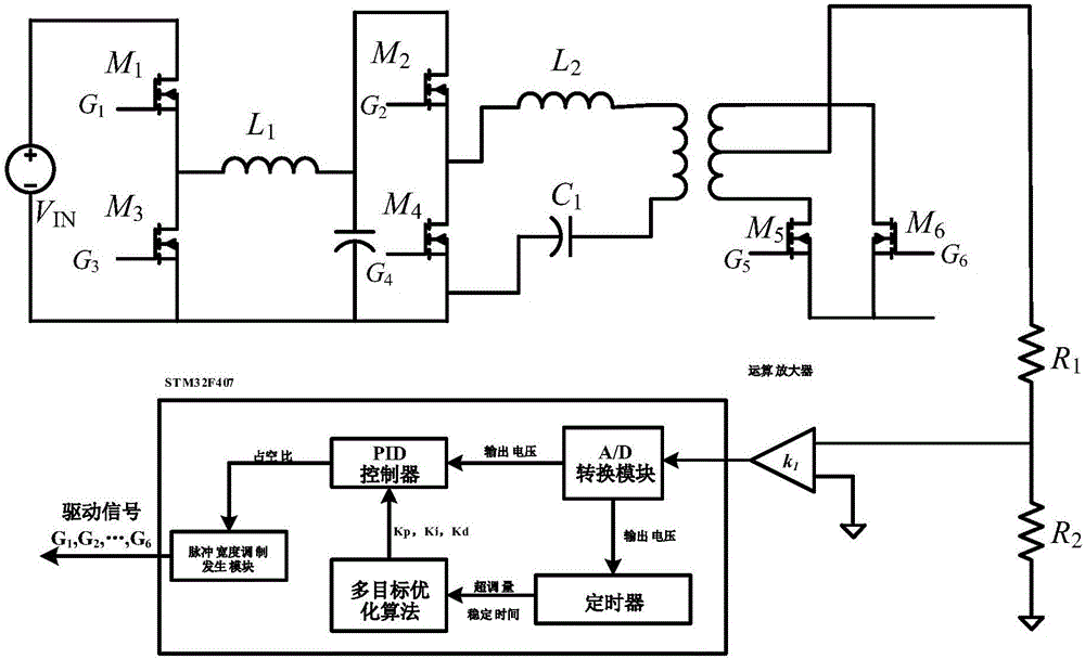
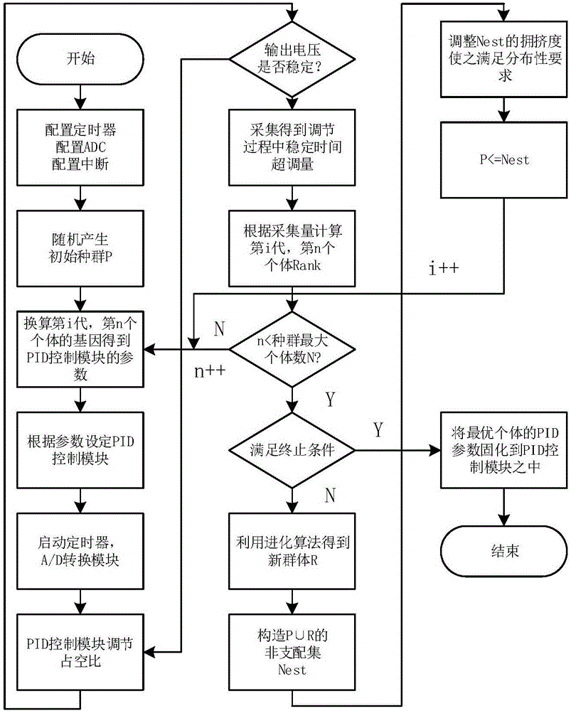
[0034] like figure 1 , 2 As shown, a switching power supply control method with dynamic response optimization is characterized in that the PID control module of the switching power supply system is used to optimize the dynamic response performance of the system by using a multi-objective optimization algorithm, including the front-stage Buck step-down topology circuit, and the rear-stage fixed Frequency LLC voltage regulation topology circuit, output voltage sampling circuit and its sampling amplification isolation circuit. And a control system composed of a control circuit with a microcontroller as the core. The output sampling circuit samples the output voltage of the rear-stage fixed-frequency LLC and then outputs it to the control circuit with the microcontroller as the core through the amplification and isolation circuit, and the outp...


PUM


Abstract

The invention discloses a switch power control method with optimized dynamic response. The method is based on a control system formed by control circuits taking a Buck step-down topological circuit, a fixed frequency LLC voltage regulating circuit, an output voltage sampling circuit and a microcontroller as control cores. Evaluation factors about dynamic response effects in a system adjusting process include overshoot in adjusting process and stabilizing time of system output voltage; a multi-objective optimization algorithm can evaluate the performance of the PID control module according to the overshoot and the stabilizing time of the system output voltage; through final iteration, the overshoot and the stabilizing time of the PID control module in the control process can reach the optimal parameter; thus the dynamic response effect of the system reaches the best.

Description

technical field [0001] The invention relates to a control method of a switching power supply, in particular to a dynamic response optimization switching power supply control method based on a multi-objective optimization algorithm. Background technique [0002] In the field of switching power supply, dynamic response is an important index to evaluate the performance of switching power supply. Improving the control method of digital power supply can improve the dynamic response capability of switching power supply. The current control methods mainly consist of three digital control methods. The first is the control method based on the linear compensator, which uses the flexibility of digital control to adjust the appropriate control parameters or the form of the compensator to make the system reach a higher level. bandwidth, while having sufficient stability margin. This control method adopts a fixed switching frequency, which can reduce noise problems, realize rapid voltage...

Claims


Application Information

Patent Timeline
Patent Type & Authority Applications(China)
IPC IPC(8): H02M3/07H02M3/335
CPCH02M3/07H02M3/33576H02M1/0003H02M3/072
Inventor 钱钦松谢明枫刘琦朱俊杰孙伟锋陆生礼时龙兴
Owner SOUTHEAST UNIV
Why Eureka
Try Eureka