Resonant pole-type soft switching inverter circuit based on auxiliary commutation of transformer

A technology of inverter circuit and resonant circuit, which is applied in the field of resonant pole soft-switching inverter circuit, can solve the problems of increased control difficulty, complexity, and auxiliary switching devices that cannot realize zero-current shutdown, and solve the change of neutral point potential problem effect

Inactive Publication Date: 2017-05-31
LIAONING UNIVERSITY OF PETROLEUM AND CHEMICAL TECHNOLOGY
View PDF1 Cites 6 Cited by
  • Summary
  • Abstract
  • Description
  • Claims
  • Application Information

AI Technical Summary

Problems solved by technology

[0004] Because of the excellent performance of the resonant pole inverter, it has been widely used in the industrial field. Various auxiliary circuit topologies have been proposed by researchers to promote the development of this type of inverter, but These topologies still have room for improvement
For example, Yao Gang and others disclosed "a new type of ZVS-ZCS inverter based on transformer-assisted commutation" in "Acta China Electrical Engineering Society" Volume 26, Issue 6, 2006. Four active auxiliary switches are used, which not only increases the volume and cost of the inverter, but also greatly increases the difficulty of controlling the inverter; Wang Qiang et al. Issue 27 disclosed "New Zero-Voltage, Zero-Current Resonant Pole Type Soft-Switching Inverter". Although the extension structure proposed in this article realizes the zero-current turn-off and zero-voltage turn-on of the main switch, the extension structure is in the DC bus. Two large-capacity electrolytic capacitors are connected in series to build the neutral point potential, so when the invert

Method used


Image

  • Resonant pole-type soft switching inverter circuit based on auxiliary commutation of transformer
  • Resonant pole-type soft switching inverter circuit based on auxiliary commutation of transformer
  • Resonant pole-type soft switching inverter circuit based on auxiliary commutation of transformer

Examples


Embodiment Construction

[0019] 1. Circuit structure

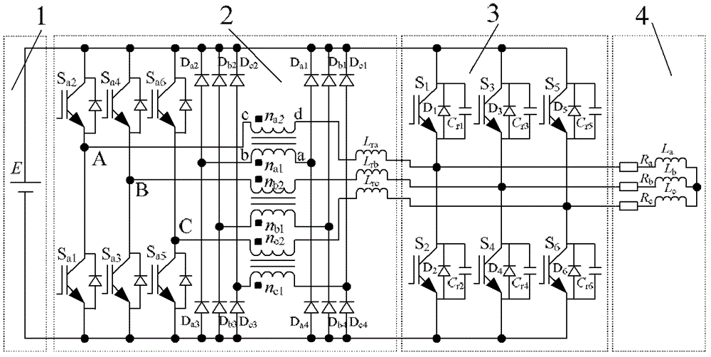
[0020] refer to figure 1 A main circuit diagram of a resonant pole type soft switching inverter circuit for transformer auxiliary commutation is provided. The main circuit includes: a DC power supply 1, an auxiliary resonant circuit 2, a three-phase inverter 3 with a buffer capacitor connected in parallel to six main switches of three bridge arms, and a resistive inductive load 4. The present invention adds three sets of identical auxiliary resonant circuits in the DC link, corresponding to the three phases (A, B, C) of the three-phase transformer, and each set of resonant circuits includes a single-phase transformer, two with anti-parallel diodes Auxiliary switch, 1 resonant inductor and 4 auxiliary diodes. Now take the auxiliary resonant circuit corresponding to inverter A as an example to introduce the structure of the resonant circuit. Auxiliary switch S a1 The emitter of the DC bus is connected to the N pole of the DC bus, and the auxilia...


PUM


Abstract

The invention relates to a resonant pole-type soft switching inverter circuit based on auxiliary commutation of a transformer. The main circuit comprises a DC power supply, a three-phase pulse width modulation inverter and a three-phase resistance-inductance load, wherein three groups of the same auxiliary resonant circuits are arranged between the DC power supply and the three-phase pulse width modulation inverter; the three groups of the auxiliary resonant circuits are corresponding to the A phase, the B phase and the C phase of a three-phase transformer; each resonant circuit group comprises one single-phase transformer, two auxiliary switches with antiparallel diodes, one resonant inductor and four auxiliary diodes. A large-capacity grading capacitor serially connected in a DC link is avoided, and the neutral point potential change problem of the inverter is solved; inductance and current thresholds related to control of auxiliary switches do not need to be set, and no extra detection and timing circuit is needed; and the transformer is used for auxiliary commutation, each phase of auxiliary circuit is only provided with two auxiliary switches, and the auxiliary switching device and the main switching device of the inverter can realize soft switching.

Description

technical field [0001] The invention belongs to the technical field of power electronics, in particular to a resonant pole type soft-switching inverter circuit for transformer auxiliary commutation. Background technique [0002] The current industrial production has higher and higher requirements for the switching frequency of the inverter, so high frequency will become the leading direction for the development of the inverter in the future, but in the hard switching inverter, the higher the switching frequency of the switching device, the higher the switching The loss will be greater, which seriously limits the development trend of high-frequency inverters. For this reason, soft switching technology has been developed rapidly. When the inverter is working at high frequency, soft switching technology can be used to realize the soft switching of the power switching devices in the inverter, thereby reducing the switching frequency of the power switching devices. losses and im...

Claims


Application Information

Patent Timeline
IPC IPC(8): H02M7/5387
CPCH02M7/5387H02M1/0058H02M7/4815Y02B70/10
Inventor 王强岳远韶韩建荣王天施刘晓琴
Owner LIAONING UNIVERSITY OF PETROLEUM AND CHEMICAL TECHNOLOGY
Why Eureka
Try Eureka