High-efficiency energy-saving dust collection equipment
A dust removal equipment, high-efficiency and energy-saving technology, applied in lighting and heating equipment, heating methods, applications, etc.
- Summary
- Abstract
- Description
- Claims
- Application Information
AI Technical Summary
Problems solved by technology
Method used
Image

Examples
Embodiment 1
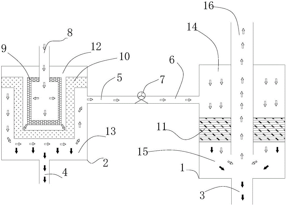
[0048] A high-efficiency energy-saving dust removal equipment, the high-efficiency energy-saving dust removal equipment includes a first-level dust removal equipment 2 and a second-level dust removal equipment 1; the first-level dust removal equipment 2 and the second-level dust removal equipment 1 are connected through pipelines, and the first-level dust removal equipment 2. The pre-filtered gas flows from the exhaust channel 5 of the first-stage dust removal equipment 2 to the air intake channel 6 of the second-stage dust removal equipment 1; The air pressure of the passage 6, and the first-stage dust removal equipment 2 is a wet dust removal equipment, so that the gas initially filtered by the first-stage dust removal equipment 2 is liquefied into mist in the second-stage dust removal equipment 1 inlet channel 6 and flows through the second-stage dust removal equipment. The demister 11 in the secondary dedusting equipment 1 is further filtered.
[0049] The demister / mist el...
Embodiment 2
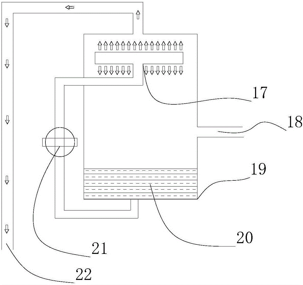
[0053] On the basis of Example 1, this embodiment further defines that the gas initially filtered by the first-stage dedusting equipment 2 is in a state of saturated water vapor in the exhaust passage 5, and the pre-filtered gas is in the air inlet passage 6 of the second-stage dedusting equipment 1. It is liquefied into mist by saturated water vapor and flows through the mist eliminator 11 in the second-stage dedusting equipment 1 for further filtration; the gas exhaust channel 5 communicates with the air humidifier 19, and the air humidifier 19 includes an atomizing nozzle 17, Normal temperature air inlet 18, water 20, high pressure water 20 pump, moisture outlet 22, normal temperature air inlet 18 is arranged in the middle of air humidifier 19, water 20 is at the bottom of air humidifier 19, high pressure water 20 pump and air humidifier 19 bottom, The atomizing nozzle 17 is in communication, and the moisture outlet 22 is in communication with the top of the air humidifier 1...
Embodiment 3
[0058] This embodiment further defines the structure of the second-stage dust removal equipment 1 on the basis of Embodiment 1 or 2. The second-stage dust removal equipment 1 includes a third space 14, a mist eliminator 11, and a fourth space 15. The device 11 divides the second-stage dedusting equipment 1 into a third space 14 and a fourth space 15, the third space 14 communicates with the air intake passage 6, and the fourth space 15 includes the second liquid outlet 3, Gas outlet 16; the mist gas liquefied into mist enters the fourth space 15 after being demistered by the demister 11 from the third space 14; after being demistered by the demister 11, the liquid flows out from the second liquid outlet 3, and the gas is Outlet 16 discharges.
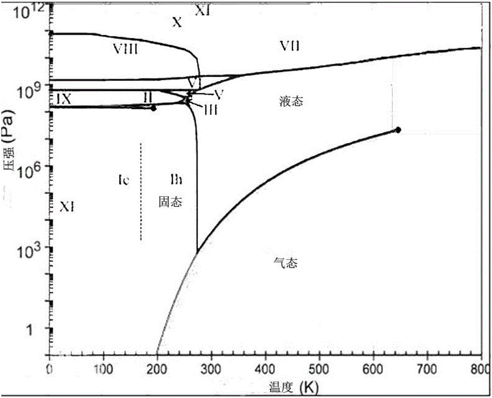
[0059] When the pressure rises, its absolute humidity will decrease, and its relative humidity will also decrease, and a part of the water vapor will be liquefied into mist (liquid state), and the water vapor will be in the form of unre...
PUM
| Property | Measurement | Unit |
|---|---|---|
| particle diameter | aaaaa | aaaaa |
Abstract
Description
Claims
Application Information
 - R&D
- Intellectual Property
- Life Sciences
- Materials
- Tech Scout
- Unparalleled Data Quality
- Higher Quality Content
- 60% Fewer Hallucinations
Browse by: Latest US Patents, China's latest patents, Technical Efficacy Thesaurus, Application Domain, Technology Topic, Popular Technical Reports.
© 2025 PatSnap. All rights reserved.Legal|Privacy policy|Modern Slavery Act Transparency Statement|Sitemap|About US| Contact US: help@patsnap.com