
Drying oven waste heat recycling system and tunnel type drying oven equipment

A waste heat recovery system and oven technology, applied in lighting and heating equipment, drying, drying machines, etc., can solve the problems of wasting energy, environmental heat pollution, etc., and achieve the effect of saving energy

Pending Publication Date: 2017-06-06
浙江桐能环保科技有限公司
View PDF10 Cites 0 Cited by
  • Summary
  • Abstract
  • Description
  • Claims
  • Application Information

AI Technical Summary

Problems solved by technology

[0003] The inventor found that the existing tunnel oven uses steam to dry, and the condensed water after one round of drying is directly removed, which wastes energy on the one hand and causes thermal pollution to the environment on the other hand

Method used


Image

  • Drying oven waste heat recycling system and tunnel type drying oven equipment
  • Drying oven waste heat recycling system and tunnel type drying oven equipment
  • Drying oven waste heat recycling system and tunnel type drying oven equipment

Examples


no. 1 example

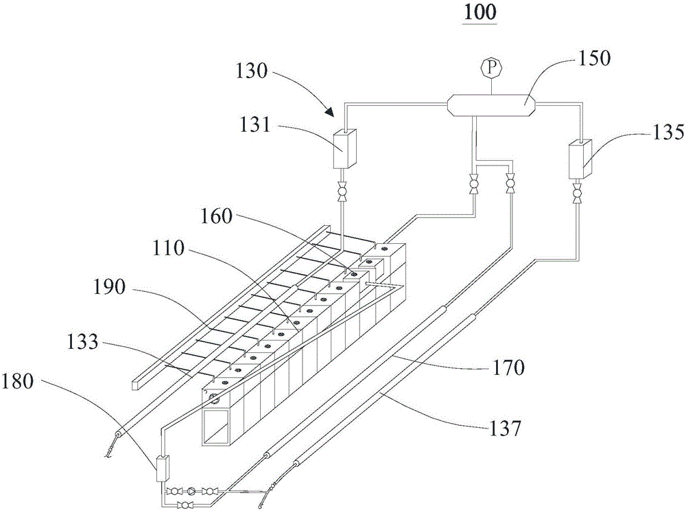
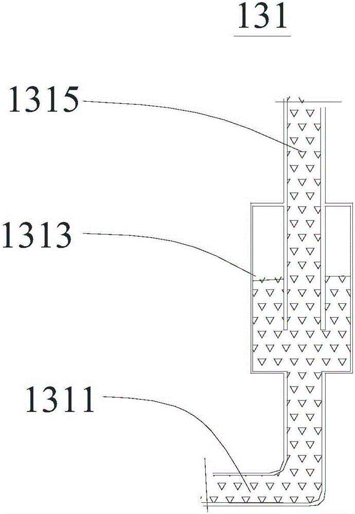
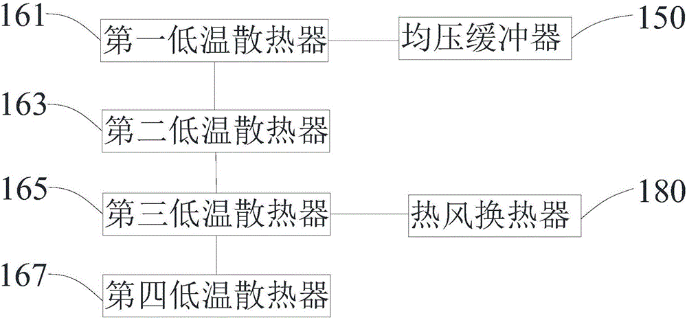
[0034] refer to figure 1 , this embodiment provides an oven waste heat recovery system 100, including an oven box 110, a lifting assembly 130, a pressure equalization buffer 150, a low-temperature heat dissipation assembly 160, a first condensate water pipeline 170, a hot air heat exchanger 180 and an exhaust gas pipe 190, one end of the oven box body 110 is connected to the pressure equalizing buffer 150, the lifting assembly 130 is connected to the pressure equalizing buffer 150, the low temperature heat dissipation assembly 160 is arranged in the oven box body 110, and the two ends of the first condensed water pipeline 170 are respectively connected to A heat dissipation circuit is formed at both ends of the low temperature heat dissipation assembly 160 , and the heat dissipation circuit communicates with the pressure equalizing buffer 150 . The hot air heat exchanger 180 is arranged between the first condensed water pipeline 170 and the oven casing 110, and one end of the ...

no. 2 example

[0049] This embodiment provides a tunnel-type oven equipment, including a drainage system (not shown) and an oven waste heat recovery system 100, wherein the basic structure, principle and technical effects of the oven waste heat recovery system 100 are the same as those of the first embodiment, which is For a brief description, for parts not mentioned in this embodiment, reference may be made to the corresponding content in the first embodiment.

[0050] In this embodiment, the drainage system communicates with the outside world, the second condensation water pipeline 133 communicates with the drainage system, and the third condensation water pipeline 137 communicates with the drainage system. At the same time, the drainage system is connected with the heat dissipation circuit, and the waste heat heat source passes through the hot air heat exchanger 180 and then is discharged to the drainage system through the steam trap, and then discharged to the outside world, which ensures...


PUM


Abstract

The invention provides a drying oven waste heat recycling system and tunnel type drying oven equipment, and relates to the field of waste heat recycling systems. The drying oven waste heat recycling system comprises a drying oven body, a lifting component, a pressure equalizing buffer, a low-temperature heat-radiation component, a first condensate water pipeline and a hot air heat exchanger, wherein the drying oven box body is connected with the pressure equalizing buffer; the lifting component is connected with the pressure equalizing buffer; the low-temperature heat-radiation component is arranged inside the drying oven body; the first condensate water pipeline and the low-temperature heat-radiation component form a heat radiation loop; the heat radiation loop is communicated with the pressure equalizing buffer; the hot air heat exchanger is arranged between the first condensate water pipeline and the drying oven body; one end of the hot air heat exchanger is communicated with the first condensate water pipeline; the other end of the hot air heat exchanger is communicated with the drying oven body. Compared with the prior art, the drying oven waste heat recycling system provided by the invention is capable of recycling waste heat sources, the utilization rate of energy can be increased, and heat pollution to the environment can be reduced.

Description

technical field [0001] The invention relates to the field of waste heat recovery systems, in particular to an oven waste heat recovery system and tunnel oven equipment. Background technique [0002] In glass fiber manufacturing, textile, chemical, chemical fiber and printing and dyeing industries, tunnel ovens are often used for drying operations. The tunnel oven generally has a long box for drying, and the tunnel oven in the above industries usually uses steam for drying. [0003] The inventor found through research that the existing tunnel oven uses steam to dry, and the condensed water after one round of drying is directly removed, which wastes energy on the one hand and causes thermal pollution to the environment on the other hand. [0004] In view of this, it is particularly important to design and manufacture an oven recycling system capable of recycling the condensed water after one round of drying. Contents of the invention [0005] The object of the present inve...

Claims


Application Information

Patent Timeline
IPC IPC(8): F26B9/06F26B21/00F26B25/00F28D7/00
CPCF26B9/06F26B21/00F26B25/00F28D7/00Y02P70/10
Inventor 钟建明
Owner 浙江桐能环保科技有限公司
Learn More