Vehicle charging device of solar power supply control

A solar power supply and car charging technology, applied in electric vehicle charging technology, solar thermal devices, solar thermal power generation and other directions, can solve the problems of exposed charging wires, waste of power resources, poor safety protection, etc. High performance and convenient operation

Active Publication Date: 2017-06-09
WM MOTOR TECH GRP CO LTD
View PDF4 Cites 21 Cited by
  • Summary
  • Abstract
  • Description
  • Claims
  • Application Information

AI Technical Summary

Problems solved by technology

The development of electric vehicles is inseparable from charging stations that supplement electric energy. Traditional charging piles have exposed charging wires that are easy to trip and cause surface wear and tear due to long-term use. Sometimes it is necessary to control the operation after power-on by the mains, resulting in a waste of power resources

Method used


Image

  • Vehicle charging device of solar power supply control
  • Vehicle charging device of solar power supply control
  • Vehicle charging device of solar power supply control

Examples


Embodiment Construction

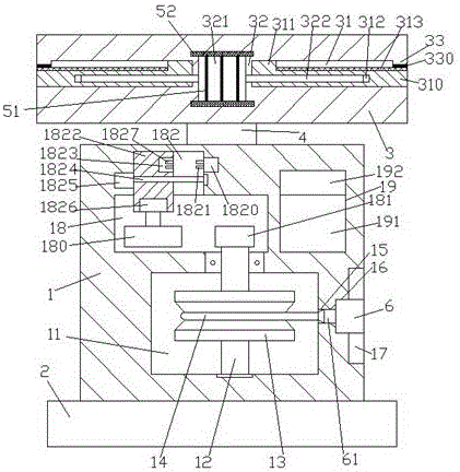
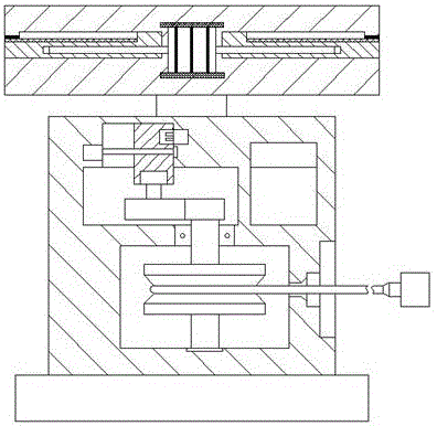
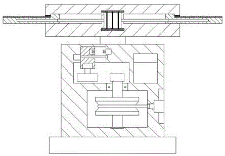
[0024] Such as Figure 1-Figure 4 As shown, a car charging device controlled by solar power supply of the present invention includes a body 1 fixed on the top of a protective base 2 and a rainproof shed 3 arranged above the body 1, and a storage cavity is provided in the body 1 11. A first cavity 18 and a second cavity 19 are provided in the body 1 at the top of the storage cavity 11, a sliding groove 182 is provided on the top wall of the first cavity 18, and the right side of the storage cavity 11 The outer wall of the body 1 on the side is provided with an operation slot 17, and a through hole 15 and a snap-in slot 16 are provided between the operation slot 17 and the storage cavity 11, and the storage cavity 11 is provided with a vertically extending Rotating shaft 12, the top extension of the rotating shaft 12 runs through the inner wall of the body 1 and extends into the first cavity 18, the end of the rotating shaft 12 in the first cavity 18 is fixed with a first Gear ...


PUM


Abstract

The invention discloses a vehicle charging device of solar power supply control. The device comprises an engine body fixed on a protection base and a weather enclosure arranged above the engine body, the engine body is internally provided with an accommodation cavity, the engine body at the top of the accommodation cavity is internally provided with a first cavity body and a second cavity body, the inner top wall of the first cavity body is provided with a slide groove, the outer wall of the engine body at the right side of the accommodation cavity is internally provided with an operation groove, a through hole and a clamping groove are formed between the operation groove and the accommodation cavity, the accommodation cavity is internally provided with a rotary shaft extending up and down, the extending section of the top portion of the rotary shaft penetrates through the inner wall of the engine body and extends into the first cavity body, the tail end of the rotary shaft in the first cavity body is fixedly provided with a first gear, the rotary shaft in the accommodation cavity is provided with an accommodation disc in the circumferential direction of the rotary shaft, a charging line twines in the accommodation disc, a sliding block is arranged in the sliding groove, the bottom of the sliding block extends into the first cavity body, and the end surface of the bottom of the sliding block is internally provided with a first motor. The vehicle charging device of solar power supply control is simple in structure and convenient to operate, can conduct wire collection work automatically, and is high in safety.

Description

technical field [0001] The invention relates to the technical field of new energy vehicle charging, in particular to a solar powered and controlled vehicle charging device. Background technique [0002] In recent years, people's demand for clean and reliable energy has increased, and "energy saving and emission reduction" in transportation has become a trend. Electric vehicles have gradually become a new hot spot for green energy saving. [0003] Automobiles are one of the main causes of the global oil crisis and greenhouse gas emissions. The emergence of electric vehicles and their rapid development represent the development direction of new energy vehicles. New technologies related to electric vehicles have become the strategic commanding heights of industrial competition in various countries , to develop high-tech products for electric vehicles and occupy the strategic commanding heights, which has great strategic significance and economic value for my country's energy se...

Claims


Application Information

Patent Timeline
Patent Type & Authority Applications(China)
IPC IPC(8): B60L11/18H02K5/24H02K9/22H02S40/10H02S20/30F24J2/52
CPCB60L53/31B60L53/51B60L2200/24F24S25/40F24S30/20H02K5/24H02K9/22H02S20/30H02S40/10Y02A30/14Y02E10/47Y02E10/50Y02T10/64Y02T10/70Y02T10/7072Y02T90/12
Inventor 梁敏华
Owner WM MOTOR TECH GRP CO LTD
Why Eureka
Try Eureka