Flattening and dust-removing composite cloth roll

A technology of composite cloth and cloth roller, which is applied in the direction of electrostatic cleaning, winding strips, cleaning methods and utensils, and can solve the problems of inability to remove impurities on the surface of textiles, non-existence, etc.

Active Publication Date: 2017-06-09
浙江玺爱纺织科技有限公司
View PDF7 Cites 30 Cited by
  • Summary
  • Abstract
  • Description
  • Claims
  • Application Information

AI Technical Summary

Problems solved by technology

[0004] Although the above-mentioned device is provided with an expansion mechanism on the cloth guide roller, it can be adjusted after the cloth guide surface is worn to make it slightly deformed, which ensures the flatness of the cloth guide roller surface and improves the quality of the product. However, there are still many technical problems in this device. First, the device only uses the e

Method used


Image

  • Flattening and dust-removing composite cloth roll
  • Flattening and dust-removing composite cloth roll
  • Flattening and dust-removing composite cloth roll

Examples


Embodiment 1

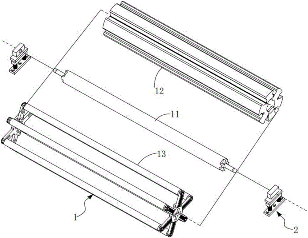
[0060] Such as figure 1 , figure 2 and image 3 As shown, this embodiment provides a flat and dust-removing composite cloth roller, including:

[0061] Roller body 1, the roller body 1 includes a main shaft unit 11, a rolling cloth roller unit 12, a telescopic cloth roller unit 13 and a brush roller unit 14, the outer side of the main shaft unit 11 is provided with a rolling cloth roller unit 12. The cloth roller unit 13 is located outside the rolling cloth roller unit 12; the two ends of the telescopic cloth roller unit 13 and the two ends of the main shaft unit 11 are fixedly connected by splicing, and the two realize synchronous rotation; The brush roller unit 14 is arranged on the outer wall of the rolling cloth roller unit 12, which is set corresponding to the telescopic cloth roller unit 13; when cleaning the brush roller unit, the rolling cloth roller unit 12 can be opposite to the The main shaft unit 11 reversely rotates, so that the rolling cloth roller unit 12 is...

Embodiment approach

[0077] Such as Figure 10 As shown, as a preferred implementation manner, the telescopic assembly 135 includes:

[0078] Slide the slider 1351 arranged in the chute 1331, the slider 1351 is embedded with a ball bearing 1352, and the slider 1351 is symmetrically sleeved on both ends of the telescopic cloth roller 134 through the ball bearing 1352 ;as well as

[0079] A telescopic spring 1353 , the telescopic spring 1353 is arranged in the sliding slot 1331 , one end of which is fixedly connected to the inner end surface of the slider 1351 , and the other end is fixedly connected to the base 131 .

[0080] It should be noted that when the rolling cloth roller unit 12 is in operation, the installation arms 133 of the telescopic cloth roller unit 13 are symmetrically arranged at both ends of the arc-shaped groove 1211, and the center line of the installation arm 133 is aligned with the center line of the arc-shaped groove 1211. Overlapping, the rolling cloth roller unit 12 and t...

Embodiment 2

[0082] image 3 , Figure 5 , Figure 9 and Figure 10 It is a structural schematic diagram of Embodiment 2 of a flat and dust-removing composite cloth roller of the present invention; Figure 9 As shown, the parts that are the same as or corresponding to those in Embodiment 1 use the reference numerals corresponding to Embodiment 1. For the sake of simplicity, only the differences from Embodiment 1 will be described below. The difference between this embodiment two and embodiment one is:

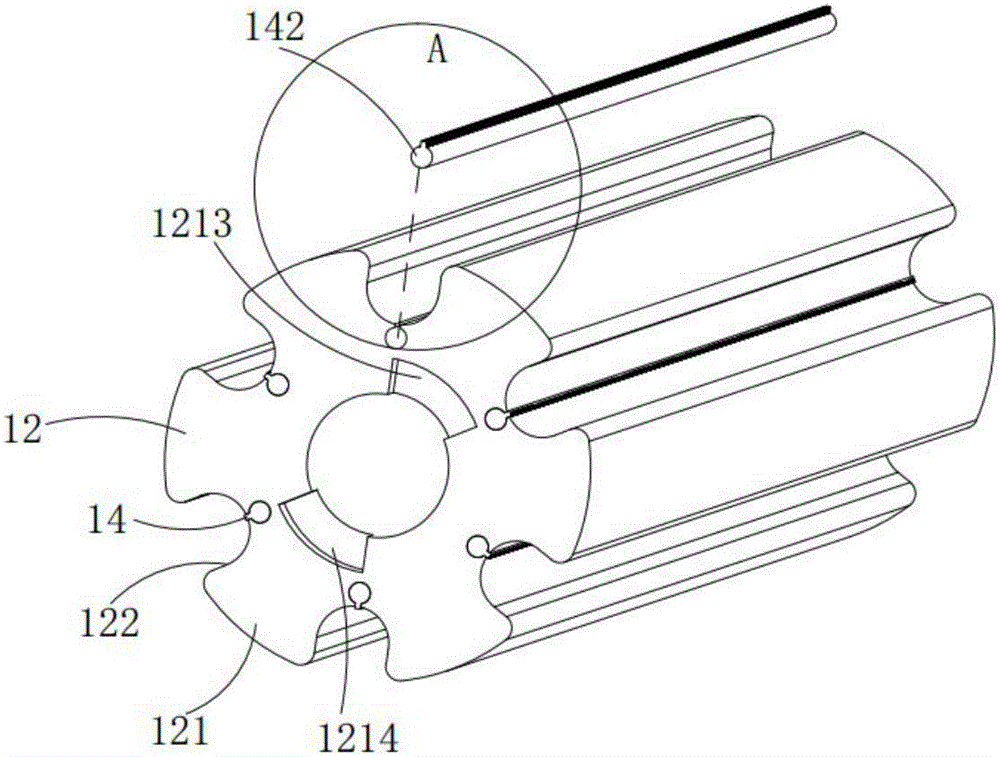
[0083] Such as image 3 shown, also includes:

[0084] Both ends of the rolling cloth roller 121 are provided with fan-shaped slots a1213 and fan-shaped slots b1214, and the fan-shaped slots a1213 and fan-shaped slots b1214 are arranged symmetrically, and the fan-shaped slots a1213 and fan-shaped slots b1214 are both arranged on opposite sides. Between two arc-shaped slots 1211 , extension lines of both sides of the fan-shaped slot a1213 and the fan-shaped slot b1214 pass through the ...


PUM


Abstract

The invention provides a flattening and dust-removing composite cloth roll. The flattening and dust-removing composite cloth roll comprises a roll body and elastic supporting seats, wherein the elastic supporting seats are symmetrically arranged at the two ends of the roll body; the roll body comprises a main shaft unit, a rolling cloth-roll unit, a telescopic cloth-roll unit and a brushing-roll unit; the rolling cloth-roll unit is sheathed at the outer side of the main shaft unit; and the telescopic cloth-roll unit is positioned at the outer side of the rolling cloth-roll unit. The flattening and dust-removing composite cloth roll provided by the invention has the advantages that by combined use of the rolling cloth-roll unit and the telescopic cloth-roll unit, when textile fabrics are rolled and flattened by the rolling cloth-roll unit, simultaneously the telescopic cloth-roll unit is utilized for carrying out friction with the textile fabrics and generating static electricity, cloth dusts and impurities on the surfaces of the textile fabrics are absorbed by utilizing the electrostatic principle, simultaneously telescopic cloth rolls are cleaned by utilizing a roll brushing unit arranged on a rolling cloth roll, and the cloth dust and the impurities on the telescopic cloth rolls are collected, so that the compounding effect of rolling, flattening, and dust and impurity removal is achieved.

Description

technical field [0001] The invention relates to the field of textile leveling and dedusting machinery, in particular to a leveling and dedusting composite cloth roller. Background technique [0002] From ancient times to the present, our daily clothing, some daily necessities and works of art are all products of textile technology. With the development of science and technology, textile knowledge and subject systems are also constantly improving. Now textiles are no longer traditional. Hand spinning and weaving are a multi-element and multi-scale structure processing technology, and an indispensable existence in our life. [0003] In the Chinese patent of Patent No. CN 103879821 A, a composite cloth guide roller is provided, which includes a cloth guide surface and a rotating shaft, and the composite cloth guide roller also includes a support mechanism, which is arranged on the cloth guide surface and Between the rotating shafts; the support mechanism includes an expansion ...

Claims


Application Information

Patent Timeline
IPC IPC(8): B65H23/26B65H23/34B65H27/00B08B6/00B08B1/04B08B1/02
CPCB08B1/02B08B1/04B08B6/00B65H23/26B65H23/34B65H27/00B65H2701/1133B65H2701/174
Inventor 倪瑞华
Owner 浙江玺爱纺织科技有限公司
Why Eureka
Try Eureka