
A chemical vapor deposition device

A technology of chemical vapor deposition and air intake chamber, which is applied in the direction of gaseous chemical plating, metal material coating process, coating, etc., to prevent the deposition of reactants, reduce equipment maintenance costs, and reduce diffusion effects

Active Publication Date: 2019-03-05
NANCHANG UNIV +1
View PDF5 Cites 0 Cited by
  • Summary
  • Abstract
  • Description
  • Claims
  • Application Information

AI Technical Summary

Problems solved by technology

It can be seen that the above-mentioned mainstream MOCVD equipment has its own advantages and disadvantages, and cannot meet the above requirements at the same time. There is a lot of room for improvement in terms of improving the utilization rate of metal organic gases and reducing the deposition on the side wall of the reaction chamber.

Method used


Image

  • A chemical vapor deposition device
  • A chemical vapor deposition device

Examples


Embodiment 1

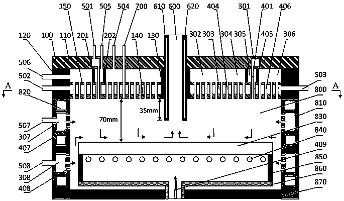
[0020] Such as figure 1 As shown, the present invention provides a chemical vapor deposition apparatus, including: a reaction chamber 800 and a shower head 100 located at the top of the reaction chamber 800 .

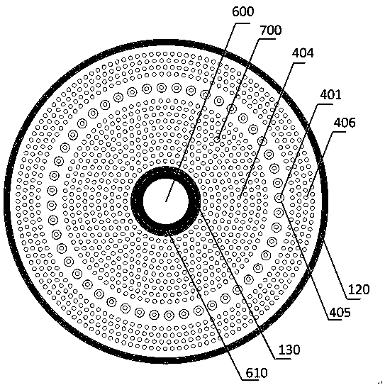
[0021] The shower head 100 includes a hollow cylinder composed of a top plate 110, an outer side wall 120, an inner side wall 130 and a bottom plate 140. An upper air inlet chamber 301 is arranged inside the top plate 110. The inside of the hollow cylinder is divided into two parts by a middle plate 150. An independent and mutually sealed part, from top to bottom is the lower air intake cavity 302 and the cooling cavity 303, wherein the lower air intake cavity 302 is divided into three parts by two vertical circular partition walls 201 and 202, along the radial direction From the center to the outside, there are an inner and lower air intake cavity 304 , a middle and lower air intake cavity 305 and an outer and lower air intake cavity 306 . The air inlet 501 of the upp...


PUM


Abstract

The invention discloses a chemical vapor deposition device. The chemical vapor deposition device comprises a spray head located at the top of a reaction cavity and the reaction cavity with side walls for purging. A metal organic gas inlet guide pipe arrayed in the spray head by a single circle is arranged in a hydride gas inlet guide pipe so that hydride gas can be transported downwards around metal organic gas, and the hydride gas or carrier gas enters the reaction cavity from gas inlet guide pipes inside and outside the spray head. Gas inlet guide pipes are arranged on the side walls of the reaction cavity and used for transporting the hydride gas or the carrier gas into the reaction cavity, and thus a purging function is achieved. A tail gas guide pipe is arranged at the center of the spray head, and reaction gas flows towards the center from the outer side in the radial direction and is finally pumped out from bottom to top through the tail gas guide pipe. By adoption of the chemical vapor deposition device, horizontal laminar flow from the outer side to the center can be formed in the reaction cavity; compared with a long-distance transportation spray head, the utilization rate of the metal organic gas can be increased greatly; compared with a short-distance transportation spray head, deposition of reactant on the side walls of the reaction cavity can be reduced greatly; and the requirement for MOCVD for production can be met.

Description

technical field [0001] The invention relates to the technical field of semiconductor manufacturing, in particular to a chemical vapor deposition device. Background technique [0002] Metal-organic compound vapor deposition (MOCVD) technology can precisely control the thickness, composition, doping and heterojunction interface of the epitaxial layer at the nanometer scale. It has become an important technical method for growing high-quality compound semiconductor thin film materials and devices, and is widely used. It has achieved industrialization in the fields of semiconductor lasers, high-brightness light-emitting diodes, solar cells, etc., especially in the fields of gallium nitride-based light-emitting diodes and lasers. [0003] At present, mainstream MOCVD equipment can be divided into vertical and horizontal reaction chambers according to the air flow channel design. Vertical reaction chambers are represented by the high-speed rotating disk reaction chamber (RDR) of ...

Claims


Application Information

Patent Timeline
Patent Type & Authority Patents(China)
IPC IPC(8): C23C16/455
CPCC23C16/45565C23C16/45574
Inventor 徐龙权丁杰张建立曹盛赵鹏罗磊江风益
Owner NANCHANG UNIV
Learn More