Boiler furnace device

A boiler furnace and furnace technology, which is applied in lighting and heating equipment, fluidized bed combustion equipment, combustion methods, etc., can solve the problems of insufficient biomass fuel combustion, easy to produce a large amount of nitrogen oxides, affecting boiler combustion efficiency, etc. Achieve the effect of improving combustion efficiency, high safety performance and strong reliability

Pending Publication Date: 2017-06-09
SUZHOU DISEN BIOLOGICAL ENERGY +1
5 Cites 2 Cited by

AI-Extracted Technical Summary

Problems solved by technology

[0003] During the use of existing biomass boilers: the existing biomass boilers are simple in structure (often using bulky refractory materials as the furnace wall), and often result in insufficient combustion of biomass fuel, an...

Method used

It should be noted that a primary air chamber is provided under the water-cooled air distribution plate; this primary air chamber is for adapting to the needs of ignition under the bed, and refractory materials are laid around it; the fire resistance and reliability of the primary air chamber can be guaranteed like this, Guarantee its long service life.
It should be noted that reinforcement beams (i.e. steel beams) are installed around the outside of the above-mentioned membrane water wall along the height direction to enhance the rigidity of the water wall and withstand fluctuations in furnace pressure, so as to avoid bearing deformation of the membrane water wall question.
The upper part of the furnace is a dilute phase zone 1, and the flue gas carries the material to continue burning, and simultaneously releases heat around the furnace. Due to the enlargement of ...

Abstract

The invention discloses a boiler furnace device which comprises a boiler furnace, wherein the upper part of the boiler furnace is a cuboidal furnace, namely, a dilute phase zone; the bottom of the boiler furnace is a conical furnace, namely, a dense phase zone; a water-cooled air distribution plate is arranged at the bottom of the conical furnace; a plurality of air caps are arranged on the surface of the water-cooled air distribution plate; a primary air compartment is also arranged at the bottom of the water-cooled air distribution plate, and the air caps on the water-cooled air distribution plate are communicated with a primary air inlet pipe; through holes in the air caps are used for introducing primary air from the primary air compartment; the conical furnace is also communicated with a secondary air inlet pipe; a wearproof layer is also arranged at the inner top of the boiler furnace; a membrane water wall is integrally arranged on the outer layer of the boiler furnace. According to the boiler furnace device, complete combustion of a biomass fuel is ensured, the combustion efficiency is improved, production of a large amount of nitrogen oxide is avoided, and the device also has the structural characteristic of the membrane water wall.

Application Domain

Fluidized bed combustionCasings/linings +1

Technology Topic

Boiler furnaceNitrogen oxides +4

Image

  • Boiler furnace device
  • Boiler furnace device

Examples

  • Experimental program(1)

Example Embodiment

[0030] The technical solutions of the present invention will be clearly and completely described below in conjunction with the accompanying drawings. Obviously, the described embodiments are part of the embodiments of the present invention, rather than all of them. Based on the embodiments of the present invention, all other embodiments obtained by those of ordinary skill in the art without creative work shall fall within the protection scope of the present invention.
[0031] In the description of the present invention, it should be noted that, unless otherwise clearly defined and limited, the term "connection" should be understood in a broad sense, for example, it can be a fixed connection, a detachable connection, or an integral connection; It is a mechanical connection or an electrical connection; it can be directly connected, or indirectly connected through an intermediate medium, and it can be the internal communication between two components. For those of ordinary skill in the art, the specific meanings of the above-mentioned terms in the present invention can be understood in specific situations.
[0032] The present invention will be further described in detail below through specific implementation examples in conjunction with the accompanying drawings.
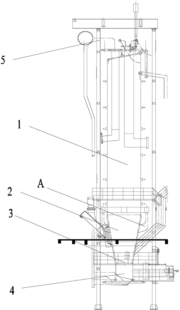
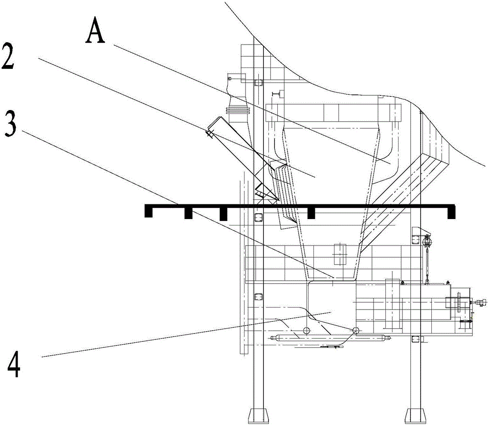
[0033] See figure 1 with figure 2 , A boiler furnace device provided by an embodiment of the present invention includes a boiler furnace;
[0034] The upper part of the boiler furnace is a cuboid-shaped furnace, that is, the dilute phase zone 1; the bottom of the boiler furnace is a cone-shaped furnace, that is, the dense-phase zone 2; and the conical opening of the cone-shaped furnace at the bottom is upward and parallel Communicate with the cuboid-shaped furnace at the top;
[0035] The bottom of the cone-shaped furnace is provided with a water-cooled air distribution plate 3; the surface of the water-cooled air distribution plate 3 is provided with several hoods; the bottom of the water-cooled air distribution plate 3 is also provided with a primary air chamber 4, and the water-cooled Several of the hoods on the air distribution plate 3 are connected with a primary air input air pipe (not shown); the through holes on the hood are used to pass in the primary air input from the primary air chamber 4; the cone-shaped The furnace is also in communication with a secondary air input air pipe (ie, secondary air port A); both the primary air input air pipe and the secondary air input air pipe are provided with a flow valve (not shown); it should be noted that , The furnace is composed of membrane water wall 5, and the lower part is a conical furnace (ie fluidized combustion section), also known as dense phase zone 2. The bottom is a water-cooled air distribution board 3, a hood is arranged on the water-cooled air distribution board 3, and a primary air chamber 4 is under the water-cooled air distribution board 3. The preheated primary air enters the dense phase area 2 through the small holes of the hood to start the fuel combustion, and blows the material away from the water-cooled air distribution plate 3. The cone-shaped furnace (ie dense phase area 2) is also connected with the secondary air input air pipe; (ie, several air pipes are drawn from the secondary air into the dense phase area 2 from the front wall, so that the fuel is evenly spread to the bed material It also strengthens the disturbance in the lower part of dense phase zone 2).
[0036] The inner top of the boiler furnace is also provided with an anti-wear layer; the outer layer of the boiler furnace is provided with a membrane water wall 5 as a whole.
[0037] The analysis of the above main structure shows that the boiler furnace is mainly composed of a rectangular parallelepiped furnace (ie rare phase zone 1) and a cone-shaped furnace (ie dense phase zone 2);
[0038] The bottom of the cone-shaped furnace is provided with a water-cooled air distribution plate 3; the surface of the water-cooled air distribution plate 3 is provided with several hoods; the bottom of the water-cooled air distribution plate 3 is also provided with a primary air chamber 4, and the water-cooled Several through holes on the air caps on the air distribution plate 3 are used to pass in primary air; the lower part of the furnace is a conical furnace (that is, the fluidized combustion section), also known as the dense phase zone 2. The bottom is a water-cooled air distribution board 3, a hood is arranged on the water-cooled air distribution board 3, and the primary air chamber 4 is under the water-cooled air distribution board 3. The preheated primary air enters the dense phase area 2 through the small holes of the hood to start the fuel combustion, and blows the material away from the water-cooled air distribution plate 3. At the same time, several air pipes are drawn from the secondary air into the dense phase zone 2, so that the fuel is evenly spread into the bed material, and at the same time, the disturbance in the lower part of the dense phase zone 2 is strengthened; in addition, the secondary air can also flow from the two above the bed The secondary tuyere A is fed into the furnace, so that the combustion can be controlled by adjusting the ratio of primary air to secondary air during operation. In this way, not only can the goal of complete combustion be achieved, but also the production of SO2 and NOx (i.e., nitrogen oxide compounds) can be controlled.
[0039] The upper part of the furnace is the dilute phase zone 1, where the flue gas carries materials and continues to burn, and at the same time releases heat around the furnace. Due to the enlarged section and the flue gas collides with the anti-wear layer of the furnace roof through the suspension section, part of the coarse material returns to the dense phase zone 2, and the flue gas carries finer materials out of the furnace and enters the cyclone separator (not shown). At the same time, the outer layer of the boiler furnace is provided with a membrane water wall 5 as a whole, which is more conducive to the protection of the boiler wall.
[0040] It should be noted that the membrane water wall is to weld a number of fin tubes in sequence along the longitudinal direction to form a whole water wall heating surface. The size of each component is welded according to the requirements of the circulating loop pipe group. When installing, the group and the group are welded and sealed, so that the furnace is tightly surrounded by a layer of water wall diaphragm.
[0041] The advantages of the membrane wall are: the membrane water wall has the most thorough protective effect on the furnace wall, so the furnace wall only needs to use insulation materials instead of refractory materials, so that the thickness and weight of the furnace wall are greatly reduced, and the furnace wall is simplified. The structure reduces the total weight of the boiler; the membrane water wall also has good airtightness, which can meet the requirements of the positive pressure combustion for the boiler, is not easy to form slag, has less air leakage, reduces the heat loss of exhaust gas, and improves the thermal efficiency of the boiler; it can be welded by the manufacturer As components leave the factory, installation is quick and easy.
[0042] The following is a detailed description of the specific structure and specific technical effects of the boiler furnace device provided by the embodiment of the present invention:
[0043] Preferably, as an implementable solution; the boiler furnace device further includes a cyclone separator; the top of the boiler furnace is also in communication with the cyclone separator.
[0044] It should be noted that in the above-mentioned boiler furnace device structure scheme, a plurality of structural forms can be selected; but in terms of practicality, it is preferable to use a cyclone dust collector and a matching bag filter; in this way, the above-mentioned cyclone dust collector is used. After dust removal and filtration, it is then filtered through multiple bag filters, so that the above-mentioned efficient and significant secondary dust removal can be achieved.
[0045] Preferably, as an implementable solution; the cross section of the cuboid-shaped hearth has a length of 4.53 m and a width of 3.23 m.
[0046] Preferably, as an implementable solution; at least two slag discharge pipes are further provided at the bottom of the water-cooled air distribution plate 3; the slag discharge pipes are used to discharge bed material and ash.
[0047] It should be noted that the above-mentioned boiler furnace adopts a full membrane wall structure. The upper part is a rectangular boiler with a cross section of 3.23×4.53m; the lower part is a cone-shaped boiler. The entire water-cooled hearth is suspended on a steel frame through a water-cooled upper header. On the top beam grid to facilitate downward expansion of the water wall.
[0048] The above-mentioned water-cooled air distribution plate mainly plays the following roles: 1. Support the bed material; 2. Make the air evenly distributed on the cross section of the entire furnace, and provide enough dynamic head to make the bed material evenly Fluidization to avoid dead zones. 3. Eliminate the large particles that are basically burnt through, have poor fluidization, and tend to deposit on the air distribution plate in time to avoid poor fluidization. The ignition method of the circulating fluidized bed boiler is to ignite the hot flue gas under the bed, which requires the air distribution system to withstand a temperature of about 800 ℃, so the air distribution device is a water-cooled air distribution device. Including: hood-type water-cooled air distribution plate and water-cooled isobaric air chamber. 1. Hood-type water-cooled air distribution board: the front wall water-cooled wall tube is bent and extended to form the water-cooled pipe of the air distribution board. Fins are welded between the water-cooled pipes to form a flower board in the usual sense. The fins are opened and installed. The hood, the intersection of the hood and the fins are all welded with reinforced sleeves to strictly fix the hood and keep the air chamber well airtight. The hoods on the water-cooling tube are arranged in line and fixed by refractory castable (266 pieces). The function of the wind cap is to make the air entering the fluidized bed produce a second split and have a certain kinetic energy to reduce the formation of initial bubbles and cause strong disturbance of the coarse particles at the bottom, avoid the deposition of coarse particles, and reduce the content of cold slag Carbon loss. It also has the effect of generating sufficient pressure drop and uniform air distribution.
[0049] Preferably, as an implementable solution; the diameter of the slag discharge pipe is 219 mm.
[0050] It should be noted that a water-cooled air distribution plate is arranged at the bottom of the furnace, and the water-cooled air distribution plate is equipped with two Φ219mm slag discharge pipes to discharge the bed material and ash.
[0051] Preferably, as an implementable solution; the surface of the membrane water wall located around the furnace in the dense phase zone is coated with a fire-resistant and anti-wear layer.
[0052] It should be noted that, in order to prevent the abrasion of the water wall, refractory and anti-wear materials are laid on the water wall around the dense phase area of ​​the boiler furnace. In this way, the fire resistance and reliability of the dense phase area of ​​the boiler furnace can be guaranteed, and its long-term service life can be guaranteed.
[0053] Preferably, as an implementable solution, a refractory layer is laid all around the primary air chamber.
[0054] It should be noted that there is a primary air chamber under the water-cooled air distribution board; in order to meet the needs of under-bed ignition, refractory materials are laid around the primary air chamber; this can ensure the fire resistance and reliability of the primary air chamber and ensure its long-term Life.
[0055] Preferably, as an implementable solution; a plurality of reinforcing beams are arranged along the vertical direction around the membrane water wall; and the plurality of reinforcing beams are welded to the membrane water wall.
[0056] Preferably, as an implementable solution; the reinforcing beam is specifically a steel beam.
[0057] It should be noted that reinforcing beams (ie steel beams) are installed along the height direction on the outer periphery of the membrane water wall to enhance the rigidity of the water wall and withstand the fluctuation of pressure in the furnace, and to avoid the problem of load-bearing deformation of the membrane water wall.
[0058] Preferably, as an implementable solution; the boiler furnace is provided with a plurality of monitoring points sequentially from top to bottom; and each of the monitoring points is provided with a flue gas temperature sensor and a flue gas pressure sensor;
[0059] The side wall of the boiler furnace is also provided with inspection doors and explosion-proof doors, and the top of the boiler furnace is also provided with a reserved denitration interface.
[0060] It should be noted that in order to monitor the operating conditions of the furnace, the flue gas temperature and flue gas pressure measuring points are arranged in several layers along the height direction. At the same time, inspection doors and explosion-proof doors are installed in appropriate locations. A denitration interface is reserved on the upper part of the furnace.
[0061] The boiler furnace device provided by the embodiment of the present invention has the following technical advantages:
[0062] 1. The boiler furnace device provided by the embodiment of the present invention guarantees the full combustion of biomass fuel, improves the combustion efficiency, and avoids the generation of a large amount of nitrogen oxides. It also has the structural characteristics of a membrane water wall.
[0063] 2. The boiler furnace device provided by the embodiment of the present invention has strong equipment reliability and high equipment safety; the above-mentioned boiler furnace device can realize full combustion treatment of biomass fuel under absolutely safe and reliable conditions, and ensure combustion Efficiency reduces the emission of pollutants.
[0064] 3. The boiler furnace device provided by the embodiment of the present invention is also composed of a water-cooled air distribution plate, a cold slag pipe, a reinforced beam, and an inspection door and an explosion-proof door. The above-mentioned boiler furnace device has a number of technical improvements, and at the same time it can bring about many technical effects.
[0065] Based on the above significant technical advantages, the boiler furnace device provided by the present invention will surely bring good market prospects and economic benefits.
[0066] Finally, it should be noted that the above embodiments are only used to illustrate the technical solutions of the present invention, but not to limit them; although the present invention has been described in detail with reference to the foregoing embodiments, those of ordinary skill in the art should understand: It is still possible to modify the technical solutions described in the foregoing embodiments, or equivalently replace some or all of the technical features; and these modifications or replacements do not make the essence of the corresponding technical solutions deviate from the technical solutions of the embodiments of the present invention. range.

PUM

PropertyMeasurementUnit
Diameter219.0mm
tensileMPa
Particle sizePa
strength10

Description & Claims & Application Information

We can also present the details of the Description, Claims and Application information to help users get a comprehensive understanding of the technical details of the patent, such as background art, summary of invention, brief description of drawings, description of embodiments, and other original content. On the other hand, users can also determine the specific scope of protection of the technology through the list of claims; as well as understand the changes in the life cycle of the technology with the presentation of the patent timeline. Login to view more.

Similar technology patents

Spray nozzle and gas turbine with same

ActiveCN104566471AImprove fire stabilityImprove combustion efficiencyContinuous combustion chamberPartially premixed combustionPower equipment
Owner:CHINA UNITED GAS TURBINE TECH CO LTD

Gas roller way kiln

Owner:青岛铸英特陶科技有限公司

Classification and recommendation of technical efficacy words

  • Improve combustion efficiency
  • Improve the quality of dust removal

Gas burner capable of adjusting gas to be self-recycling

Owner:GUANGZHOU INST OF ENERGY CONVERSION - CHINESE ACAD OF SCI

Biomass solid formed fuel anti-slagging additive and preparation method thereof

Owner:ACADEMY OF PLANNING & DESIGNING OF THE MINIST OF AGRI
Why Eureka
Try Eureka