Low-profile low-cross-polarization dual-polarized broadband antenna

A broadband antenna, dual-polarization technology, applied in the microwave field, can solve performance constraints, limited plane form, and microstrip antenna bandwidth less than 10%, etc., to achieve the effect of improving performance

Inactive Publication Date: 2017-06-09
CHINA ELECTRONIC TECH GRP CORP NO 38 RES INST
View PDF0 Cites 21 Cited by
  • Summary
  • Abstract
  • Description
  • Claims
  • Application Information

AI Technical Summary

Problems solved by technology

[0003] Microstrip patch antennas are widely used in antenna design because of their light weight, small size, low cost, and low processing difficulty. However, due to their planar form, the bandwidth of traditional microstrip antennas is often less than 10%. Performance is limited when a certain frequency bandwidth and wide-angle scanning are required
Secondly, because the microstrip form is prone to spurious radiation, the cross-polarization of traditional broadband microstrip antennas is generally only -10dB ~ -20dB

Method used


Image

  • Low-profile low-cross-polarization dual-polarized broadband antenna
  • Low-profile low-cross-polarization dual-polarized broadband antenna
  • Low-profile low-cross-polarization dual-polarized broadband antenna

Examples


Embodiment 1

[0029] A dual-polarized broadband antenna with low cross-section and low cross-polarization, the working frequency is 1.0-1.9GHz, the polarization mode is horizontal polarization and vertical polarization, and the free-space wavelength of the center frequency point lambda 0 About 207mm.

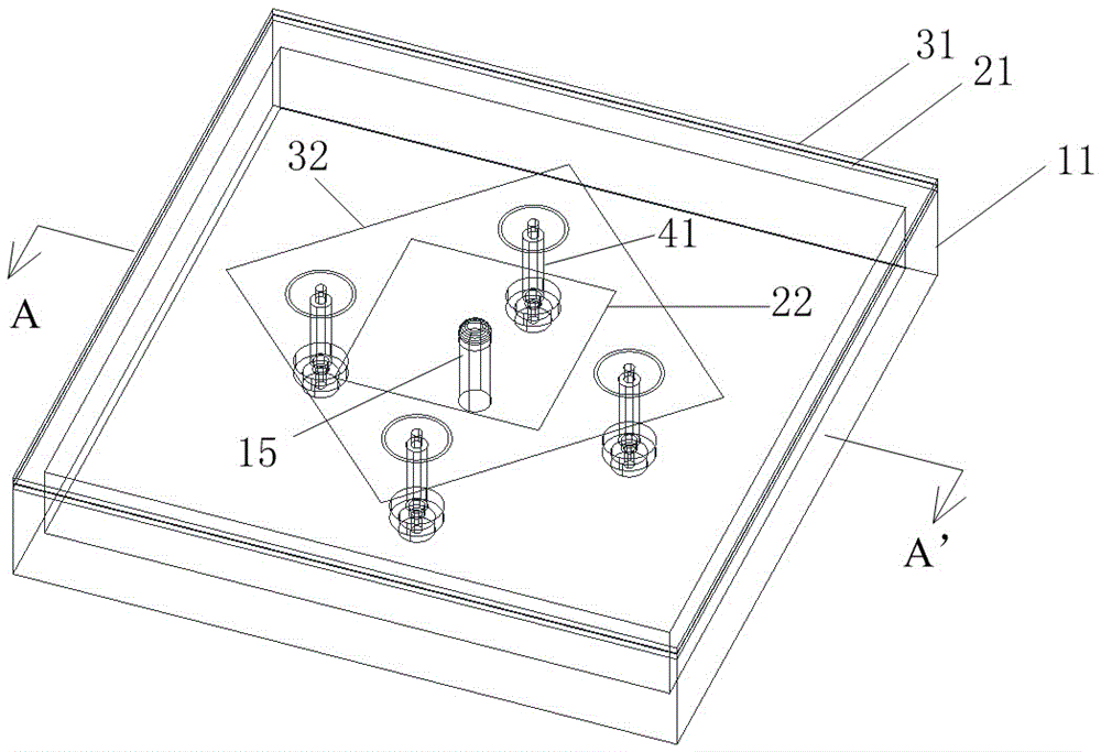
[0030] see figure 1 A dual-polarized broadband antenna with low cross-section and low cross-polarization includes a rectangular flat box-shaped resonant cavity 11 with an open top, an upper microstrip plate 31, a lower microstrip plate 21, four feeding probes 41 and the same Shaft medium 13; the cavity length and width of the resonance cavity 11 are both 122 mm, and the cavity depth is 15 mm.

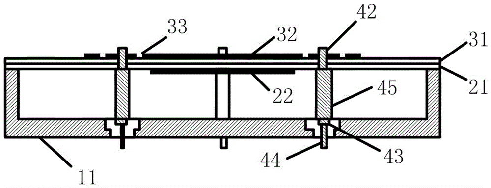
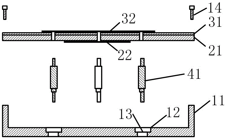
[0031] see figure 2 with image 3 , the upper microstrip board 31 and the lower microstrip board 21 are overlapped and glued up and down and mounted on the top opening of the resonant cavity 11, and the edges are fixed with screws 14. The material of the upper microstrip plate 31 and the lower f...

Embodiment 2

[0040] see Figure 9 , an antenna array composed of 3 antenna units, the distance between the centers of adjacent antenna units is 121 mm; the metal wall thickness between the resonant cavities 11 of adjacent antennas is 6 mm. The designed working bandwidth of this antenna array is 15%, so a single-layer radiating microstrip board is used, that is, only the upper layer of microstrip board 31 and the upper layer of copper foil patch 32 are provided, without the need for the lower layer of microstrip board 21 and the lower layer of copper foil patch twenty two.

[0041] see Figure 10 , sx1, sx2, sx3 are the relative distances between the two feeding points in the horizontal polarization direction on the radiating microstrip board of the 1st, 2nd, and 3rd antenna elements, respectively, sy1, sy2, sy3 are the relative distances between the two feed points in the vertical polarization direction on the radiating microstrip board of the first, second, and third antenna elements...


PUM


Abstract

The invention relates to a low-profile low-cross-polarization dual-polarized broadband antenna comprising a resonant cavity, an upper microstrip board, a lower microstrip board, four feed probes and a coaxial medium. A rectangular upper-layer copper foil paster is arranged at the middle of the top surface of the upper microstrip board; and a rectangular lower-layer copper foil paster is arranged at the middle of the bottom surface of the lower microstrip board. The four feed probes distributed in the resonant cavity uniformly enable the upper-layer copper foil paster to be transited to the bottom of the resonant cavity vertically in a feed mode and, together with the coaxial medium, form a coaxial radio-frequency connection port. And a 45-degree angle is formed between each side of the upper-layer copper foil paster and each side of the resonant cavity. The profile height of the dual-polarized broadband antenna is 0.1-0.15 lambda0, wherein the lambda0 expresses a free space wavelength of a central frequency point. Therefore, the antenna unit performance can be improved obviously and thus the work bandwidh reaches 60%. More than two low-profile low-cross-polarization dual-polarized broadband antennas are connected in parallel to form a low-profile low-cross-polarization dual-polarized broadband antenna array.

Description

technical field [0001] The invention belongs to the field of microwave technology, and can also be used in the fields of microwave communication, modern radar systems, electronic equipment, etc., and specifically relates to a dual-polarization broadband antenna. Background technique [0002] Antenna is one of the most important components of systems such as wireless broadcasting, wireless communication and wireless detection. As the core of wireless technology, the structure and characteristics of the antenna system determine the working performance of the entire system to a large extent. With the rapid development of active phased array technology, radar and other systems have higher and higher requirements for frequency bandwidth and scanning angle, which also puts forward more and more requirements for the function and performance of the antenna. [0003] Microstrip patch antennas are widely used in antenna design because of their light weight, small size, low cost, and l...

Claims


Application Information

Patent Timeline
Patent Type & Authority Applications(China)
IPC IPC(8): H01Q1/38H01Q1/50H01Q15/24H01Q21/00
CPCH01Q1/38H01Q1/50H01Q15/24H01Q21/00
Inventor 周子成李雁姚雨帆卢晓鹏
Owner CHINA ELECTRONIC TECH GRP CORP NO 38 RES INST
Why Eureka
Try Eureka