Plasma-facilitated photocatalytic purification device and purification method

A purification device and photocatalytic technology, applied in chemical instruments and methods, separation methods, output power conversion devices, etc., can solve problems such as high operating costs, large exhaust gas odor, environmental pollution, etc., to reduce organic pollutants, use Low cost and the effect of improving the environmental protection level

Pending Publication Date: 2017-06-13
上海巨浪环保科技发展有限公司
View PDF7 Cites 4 Cited by
  • Summary
  • Abstract
  • Description
  • Claims
  • Application Information

AI Technical Summary

Problems solved by technology

Especially in chemical plants, steel plants, pharmaceutical plants, coking plants and oil refineries, etc., the exhaust gas emitted is very smelly, which seriously pollutes the environment and affects human health; while organic pollutants are one of the most harmful gases in the exhaust gas. Pollutants refer to pollutants composed of natural organic substances in the form of carbohydrates, proteins, amino acids, and fats, and some other biodegradable synthetic organic substances; the existing technologies for the treatment of organic pollutants mainly It is through physical adsorption or electrostatic adsorption, but the above methods have a limited degree of treatment of organic pollutants and high operating costs. Therefore, ordinary factories generally abandon the above methods and directly discharge the exhaust gas to the outside, causing damage to the surrounding environment and the health of residents. cause damage

Method used


Image

  • Plasma-facilitated photocatalytic purification device and purification method
  • Plasma-facilitated photocatalytic purification device and purification method

Examples


Embodiment Construction

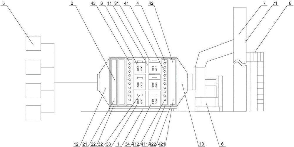
[0045] The specific implementation manners of the present invention will be further described below in conjunction with the drawings and examples. The following examples are only used to illustrate the technical solution of the present invention more clearly, but not to limit the protection scope of the present invention.

[0046] Such as figure 1 with figure 2 Shown, the present invention is a kind of plasma cooperative photocatalytic purification device, comprises casing 1, filter layer 2, plasma layer 3 and photochemical layer 4; Inside casing 1 has the channel 11 that connects casing 1 two ends, filter layer 2, The plasma layer 3 and the chemical layer are sequentially fixed in the channel 11; one end of the channel 11 is an inlet 12;

[0047] The other end of passage 11 is outlet 13, and filter layer 2 is fixed on passage 11 on one end towards inlet 12, and plasma layer 3 is fixed in the passage 11 of the side of filter layer 2 facing away from inlet 12, and photochemi...


PUM


Abstract

The invention discloses a plasma-synergized photocatalytic purification device and a plasma-synergized photocatalytic purification method. The plasma-synergized photocatalytic purification device comprises a box body, a filter layer, a plasma layer and a photochemical layer, wherein a passage communicated with the two ends of the box body is formed inside the box body; the filter layer, the plasma layer and the photochemical layer are sequentially fixed into the passage; the photochemical layer comprises an UV optical layer and a catalyst layer; the UV optical layer is positioned on one side, facing the filter layer, of the photochemical layer; the catalyst layer is positioned on one side, back from the filter layer, of the photochemical layer. The plasma-synergized photocatalytic purification device has the advantages and beneficial effects as follows: the plasma-synergized photocatalytic purification device is simple in structure and low in using cost, and can greatly reduce or even completely eliminate organic pollutants in waste gas emitted in a factory and discharge water and carbon dioxide which are harmless to the environment, so that the environmental protection level of the factory is improved, the environment around the factory is avoided from being damaged by the organic pollutants, and the body health of residents around the factory is protected.

Description

technical field [0001] The invention relates to the field of environmental protection equipment, in particular to a plasma cooperative photocatalytic purification device and a purification method. Background technique [0002] Exhaust gas refers to the poisonous and harmful gas emitted by human beings in the process of production and life. Especially in chemical plants, steel plants, pharmaceutical plants, coking plants and oil refineries, etc., the exhaust gas emitted is very smelly, which seriously pollutes the environment and affects human health; while organic pollutants are one of the most harmful gases in the exhaust gas. Pollutants refer to pollutants composed of natural organic substances in the form of carbohydrates, proteins, amino acids, and fats, and some other biodegradable synthetic organic substances; the existing technologies for the treatment of organic pollutants mainly It is through physical adsorption or electrostatic adsorption, but the above methods ha...

Claims


Application Information

Patent Timeline
IPC IPC(8): B01D53/86B01D53/72H02M5/458H02M7/5383
CPCB01D53/007B01D53/323B01D53/8668H02M5/458H02M7/53832B01D2255/20707B01D2255/802B01D2259/804
Inventor 尤政辉安心曹旦王振华徐璐汤志涛许德旺
Owner 上海巨浪环保科技发展有限公司
Why Eureka
Try Eureka