Rubber forming method and rubber forming mould of high-curvature high-flanging sheet metal part

A technology of sheet metal parts and forming dies, which is applied in the field of aircraft manufacturing, can solve problems such as the inability to freely undulate in the thickness direction of materials, the structural limitations of large curvature flanged parts, and the wrinkling of convex flanged parts, etc., to achieve simple and convenient installation and operation methods , Reduce the workload of knocking and edge finishing, and the effect of low level dependence

Active Publication Date: 2017-06-13
XIAN AIRCRAFT IND GROUP
View PDF7 Cites 10 Cited by
  • Summary
  • Abstract
  • Description
  • Claims
  • Application Information

AI Technical Summary

Problems solved by technology

[0004] In order to improve the forming quality of aircraft "fish head-shaped" sheet metal parts, reduce the amount of manual edge trimming, solve the defect that the side pressing block wrinkle elimination method cannot be formed by expanding blanks, and the structural restrictions on forming large curvature flanging parts, the present invention The purpose of this paper is to provide a rubber forming method and forming die for sheet metal parts with large curvature and high flanging
[0006] The beneficial effects of the present invention are: 1) The forming die of the present invention adopts a rubber container frame combination structure with a pressing plate and a support plate, so that the flanging part of the sheet material is always clamped during the rubber hydraulic process, and the material cannot be clamped in the thickness direction. Free undulation, solves the problem of wrinkling and forming difficulties of convex and bent parts

Method used


Image

  • Rubber forming method and rubber forming mould of high-curvature high-flanging sheet metal part
  • Rubber forming method and rubber forming mould of high-curvature high-flanging sheet metal part
  • Rubber forming method and rubber forming mould of high-curvature high-flanging sheet metal part

Examples


Embodiment Construction

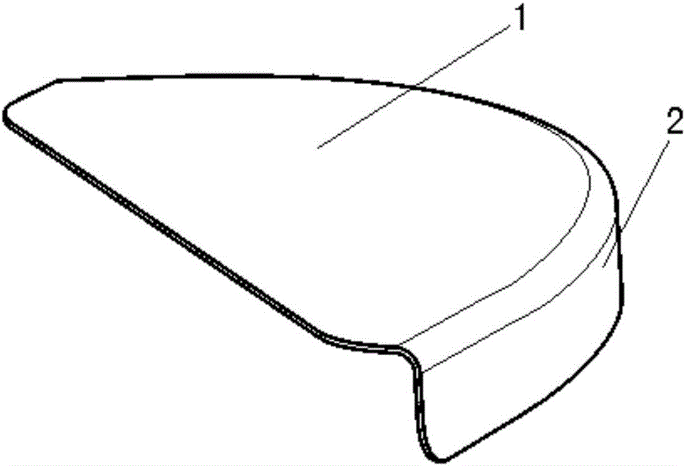
[0015] Referring to the accompanying drawings, the aircraft parts provided by the embodiment are as figure 1 As shown, the part 1 is a sheet metal part with a convex curve and high flanging, and the part is in the shape of a "fish head". The biggest problem with the forming of the existing technology is that the flanging surface 2 is prone to wrinkles or even dead wrinkles during the forming of the part. , the amount of manual correction is large, and the surface quality is poor.

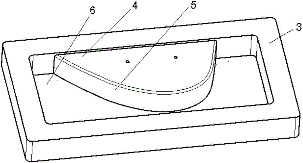
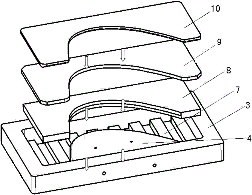
[0016] The molding die that the present application proposes is as shown in the figure, and the molding die contains a container frame 3, a molding die 4, a pressing plate 10, a support plate 9 and a rubber cushion block 7, and the described container frame 3 is a cuboid frame, and the described molding die 4 is a module that matches the sheet metal part 1, the working surface 5 on the outer side of the forming die 4 matches the inner side of the flanging surface 2 of the sheet metal part 1, and the...


PUM


Abstract

The invention discloses a rubber forming method and a rubber forming mould of a high-curvature high-flanging sheet metal part. The rubber forming mould comprises an accommodating box, a forming die, a pressing plate, a supporting plate and rubber pads, wherein the non-working surface on the inner side of the forming die is connected to the inner wall of one side of the accommodating box; a moulding cavity is formed between the working surface on the outer side of the forming die and the inner wall of the accommodating box; the outlines of the pressing plate and the supporting plate are smaller than the outline of the moulding cavity; the inner sides of the pressing plate and the supporting plate are matched with the working surface on the outer side of the forming die. The rubber forming method comprises the following steps: placing the accommodating box on a workbench of a hydraulic machine, placing a plurality of rubber pads with equal height inside the moulding cavity, and placing the supporting plate on the upper surfaces of the rubber pads so as to make the surface height of the supporting plate consistent with the height of the forming die; overlapping the pressing plate and the supporting plate, and clamping a flanging area of an unfolded blank; downwardly pressing the pressing plate by using hydraulic forming equipment, fitting the flanging area of the unfolded blank with the working mould surface of the forming die, and forming.

Description

technical field [0001] The invention relates to sheet metal part forming technology in the field of aircraft manufacturing, in particular to a forming method and a forming die for sheet metal parts with large curvature and high flanging. Background technique [0002] In recent years, the degree of mechanization of sheet metal forming in the domestic aviation field has become higher and higher. As an advanced flexible sheet metal forming technology, hydraulic rubber bag forming technology has become more and more Favored, especially suitable for the production of many varieties and small batches of products. [0003] The sheet metal parts involved in this application are common sheet metal parts in aircraft manufacturing. This type of parts is commonly found in the fixed front edge of large aircraft. It is distributed along the direction of the wingspan and has a structure similar to a "fish head". It is a compression flange with a convex curvature. During the forming proce...

Claims


Application Information

Patent Timeline
Patent Type & Authority Applications(China)
IPC IPC(8): B21C25/02B21C26/00
CPCB21C25/02B21C26/00
Inventor 白颖李世峰雷颖洁
Owner XIAN AIRCRAFT IND GROUP
Why Eureka
Try Eureka