
Vacuum pumping side-pressing mechanism for manufacturing water-cooled clutch casing

A clutch housing and vacuum pumping technology, which is applied in the field of die-casting molds, can solve problems such as air leakage, reduce the strength of castings, and unfavorable high-efficiency production, so as to ensure the overall quality and avoid shrinkage cavities.

Active Publication Date: 2017-06-13
ZDM ZHENZHI MACHINERY & MOLD
View PDF10 Cites 0 Cited by
  • Summary
  • Abstract
  • Description
  • Claims
  • Application Information

AI Technical Summary

Problems solved by technology

[0002] In the domestic die-casting field, air cooling is mostly used for mold cooling. With the development of cooling technology, natural room temperature full water cooling has become a new cooling method for die-casting molds. However, in this method, the mold inlet water temperature is not constant, and the cooling effect is unstable. If the temperature deviation is large, shrinkage and shrinkage cavities are prone to occur. Operators often rely on experience within the scope of the instruction book to estimate and set parameters such as cooling time, which is not conducive to stabilizing the casting process, is not conducive to efficient production, and affects output and quality.
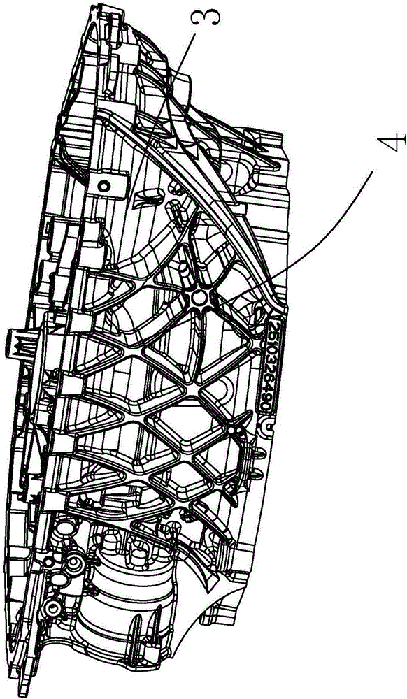
such as production figure 1 Zhongde clutch housing 3 products, here in the thermoforming process, because there are many irregular raised positions 4 around the outer surface of the clutch, if the die-casting process is not controlled, the raised structures will be formed Partial shrinkage cavity and shrinkage porosity directly reduce the strength of the casting, water leakage and air leakage in the pressure test of the casting, and voids appear on the machined surface, resulting in unqualified castings

Method used


Image

  • Vacuum pumping side-pressing mechanism for manufacturing water-cooled clutch casing
  • Vacuum pumping side-pressing mechanism for manufacturing water-cooled clutch casing
  • Vacuum pumping side-pressing mechanism for manufacturing water-cooled clutch casing

Examples


Embodiment Construction

[0018] The following are specific embodiments of the present invention and in conjunction with the accompanying drawings, the technical solutions of the present invention are further described, but the present invention is not limited to these embodiments.

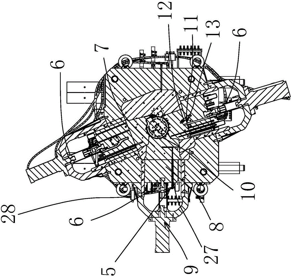
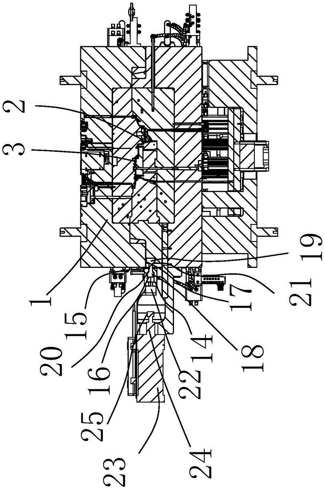
[0019] In the figure, die-casting mold 1; injection mold cavity 2; clutch housing 3; protruding position 4; valve type vacuum device 5; side pressure device 6; side pressure top block 7; side pressure auxiliary driving block 8; side pressure driving parts 9; side pressure plug 10; oblique fixed adjustment piece 11; first oblique adjustment groove 12; second oblique adjustment groove 13; hedging piece 14; hedging rod 15; main buckle groove 16; from buckle groove 17; first Set of chucks 18; second set of chucks 19; outer limiting convex edge 20; inner limiting convex edge 21; top pressure inlet groove 22; side pressure cylinder 23; side pressure air rod 24; raised step head 25; vacuum valve 26; Vacuum tube 27.

[0020] Such...


PUM


Abstract

The invention belongs to the technical field of a die-casting die and provides a vacuum pumping side-pressing mechanism for manufacturing a water-cooled clutch casing. The vacuum pumping side-pressing mechanism is arranged on the side edge of the die-casting die; the clutch casing is arranged in an injection die cavity of the die-casting die; three the vacuum pumping side-pressing mechanisms are adopted and are propped against bulge positions of the clutch casing in the injection die cavity, each vacuum pumping side-pressing mechanism comprises a valve type vacuum pumping device and a side-pressing device, the valve type vacuum pumping device communicates with the injection die cavity and is used for performing vacuum pumping actions, and the side-pressing device is linked with the valve type vacuum pumping device and used for extruding the corresponding bulge position of the clutch casing, so that the bulge position performs feeding after being subjected to extrusion pressure. The vacuum pumping side-pressing mechanism has the advantages as follows: the multiple side-pressing mechanisms are adopted and combined with the oil cylinder driven valve type vacuum pumping, so that phenomena of shrinkage cavity and shrinkage porosity in the surface of a casting are avoided, and the overall quality of the clutch casing is guaranteed.

Description

technical field [0001] The invention belongs to the technical field of die-casting molds, in particular to a vacuum side pressure mechanism for manufacturing water-cooled clutch housings. Background technique [0002] In the domestic die-casting field, air cooling is mostly used for mold cooling. With the development of cooling technology, natural room temperature full water cooling has become a new cooling method for die-casting molds. However, in this method, the mold inlet water temperature is not constant, and the cooling effect is unstable. If the temperature deviation is large, it is easy to produce shrinkage, shrinkage and cavities. Operators often rely on experience to estimate and set cooling time and other parameters within the scope of the instruction book, which is not conducive to stable casting process, not conducive to efficient production, and affects output and quality. such as production figure 1 Zhongde clutch housing 3 products, here in the thermoforming...

Claims


Application Information

Patent Timeline
IPC IPC(8): B22D17/14B22D17/20
CPCB22D17/145B22D17/2069
Inventor 徐挺唐卫平莫志好
Owner ZDM ZHENZHI MACHINERY & MOLD
Learn More