
Device and method for monitoring a workspace for laser material processing

A monitoring device, optical device technology, applied in the direction of measuring device, auxiliary device, laser welding equipment, etc., can solve the problems of not ensuring enough reliable monitoring, complex and expensive, etc.

Active Publication Date: 2019-06-07
LESSMULLER LASERTECHN
View PDF14 Cites 0 Cited by
  • Summary
  • Abstract
  • Description
  • Claims
  • Application Information

AI Technical Summary

Problems solved by technology

[0006] However, it has been shown that the known solutions do not ensure a sufficiently reliable monitoring in all processing situations and also often require complex and expensive installation measures

Method used


Image

  • Device and method for monitoring a workspace for laser material processing
  • Device and method for monitoring a workspace for laser material processing
  • Device and method for monitoring a workspace for laser material processing

Examples


Embodiment Construction

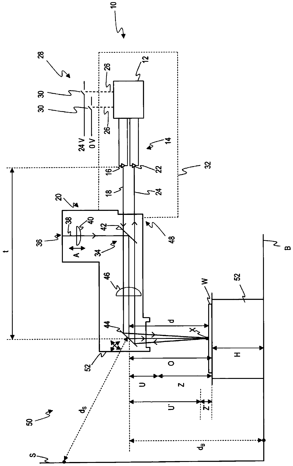
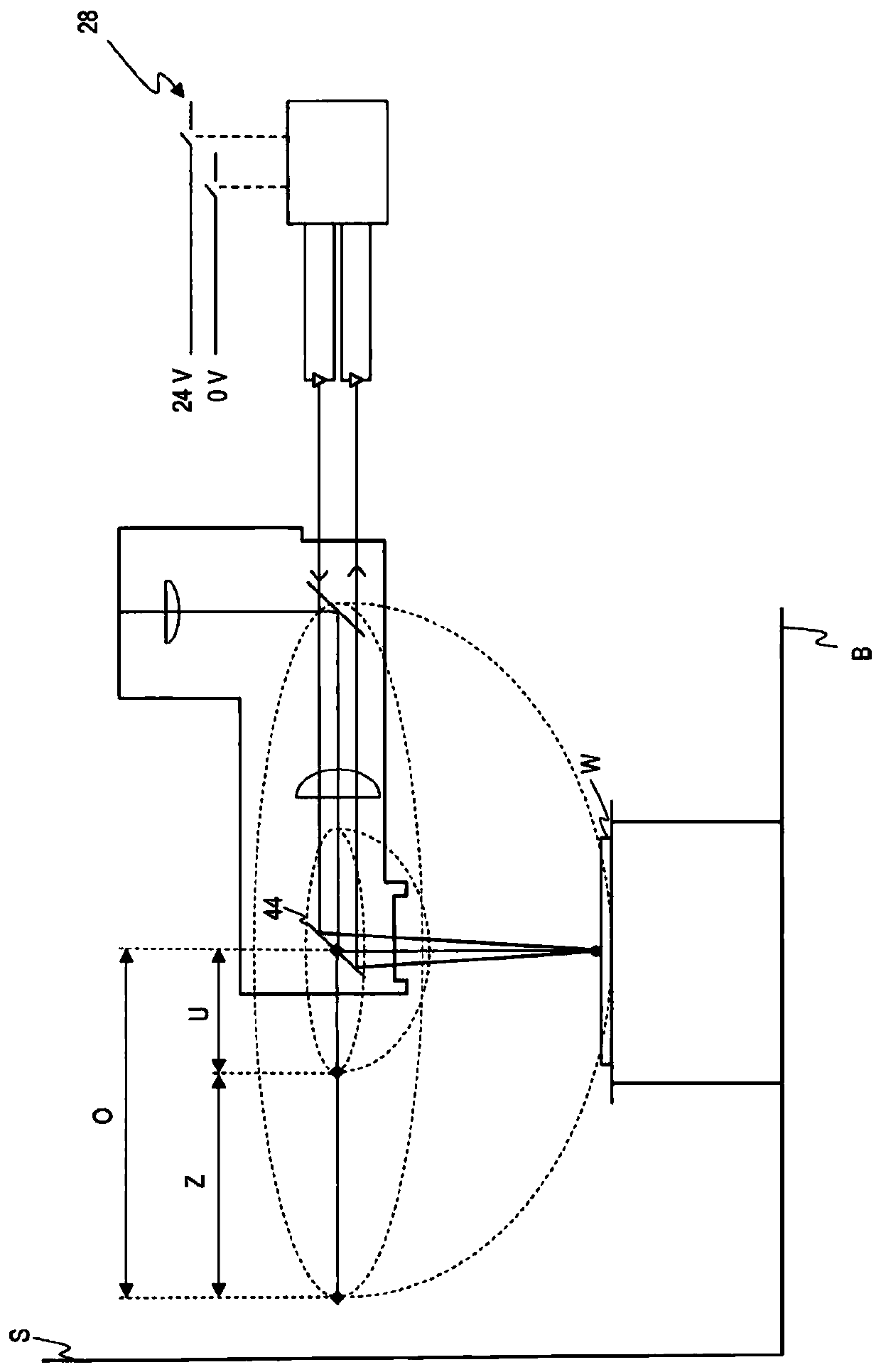
[0062] figure 1 A monitoring device according to the invention is shown and generally designated 10 . The monitoring device 10 includes an arithmetic unit 12 including a determination unit not shown separately. The computing unit 12 is connected to a measuring unit 14 , which in the present case is designed as an optical distance measuring unit in the form of a time-of-flight sensor device. In detail, the measuring unit 14 comprises a measuring beam source in the form of a laser diode 16 which emits measuring beam pulses 18 in the direction of the laser welding head 20 . Furthermore, the measuring unit 14 includes a recording unit in the form of a photodiode 22 , by means of which a measuring beam component 24 reflected by the environment can be detected.

[0063] It can also be seen that the computing unit 12 is connected to a power source 28 of the laser processing system, not shown separately, via a communication link 26 shown in dotted lines. More precisely, the computi...


PUM


Abstract

The invention relates to a monitoring device for a machining system for machining workpieces by means of a high-energy machining beam, in particular in a spatially restricted machining area, wherein the monitoring device comprises a measuring beam for supplying a measuring beam source, and a recording unit for detecting the measurement beam component reflected by the environment, wherein the monitoring device is arranged to couple the measurement beam into the processing beam optics of the processing system, so that the measurement beam and the processing beam can be directed into the environment co-location, wherein the monitoring device is also configured to derive at least one distance value from the measured reflected component of the measuring beam from which the distance of the processing beam optics from the ambient area reflecting the measuring beam can be deduced, And wherein, the monitoring device further includes a judging unit, which is used for judging whether the measured distance value is within the allowable distance value range.

Description

technical field [0001] The invention relates to a monitoring device for a machining system for machining workpieces by means of a high-energy machining beam, in particular in a spatially restricted machining area. The high-energy processing beam is preferably a laser beam, and the processing system is preferably a laser processing system, eg for welding or cutting workpieces. Background technique [0002] The processing beams of such processing systems are often a significant source of hazard. For example, by stray reflections or incorrect orientation of the processing beam, extensive damage can be caused in the area of ​​the processing system. It is therefore known to provide so-called safe rooms, which form a device consisting of a protective wall surrounding the processing system. In other words, the processing area or the working space of the processing system is spatially restricted in a targeted manner in order to block the high-energy processing beams and protect th...

Claims


Application Information

Patent Timeline
Patent Type & Authority Patents(China)
IPC IPC(8): B23K26/03B23K26/046G01S17/08G01S17/88
CPCB23K26/03B23K26/046G01S17/08G01S17/88B23K37/006B23K26/032B23K26/702G01S7/4808
Inventor E·莱斯穆勒C·特鲁克恩布罗德
Owner LESSMULLER LASERTECHN
Learn More