Tubing plunger

A plunger and oil pipe technology, applied in the field of oil extraction equipment, can solve the problems of increasing sliding friction, sliding friction and wear of the inner wall of the plunger oil pipe, etc., so as to increase the sliding friction, reduce the risk of oil leakage and water leakage, and improve the service life long effect

Active Publication Date: 2018-11-09
SICHUAN ANJIE OIL GAS TECHNICAL SERVICE CO LTD
View PDF5 Cites 1 Cited by
  • Summary
  • Abstract
  • Description
  • Claims
  • Application Information

AI Technical Summary

Problems solved by technology

[0003] However, the plunger has the following problems. When the plunger passes through the curved part of the oil pipe in the directional well, it always closely fits the inner wall of the oil pipe on the outer side of the bend of the oil pipe, increasing the sliding friction force at this place. When the plunger works in the oil well, Repeatedly passing through this bend, the sliding friction between the plunger and the inner wall of the oil pipe at this place is seriously worn

Method used


Image

  • Tubing plunger
  • Tubing plunger

Examples


Embodiment 1

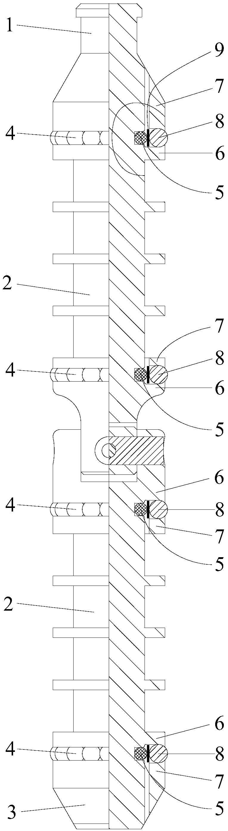
[0027] like Figure 1-2 As shown, a tubing plunger according to the present invention includes a fishing head 1 , a guiding head 3 and at least one plunger section 2 .

[0028] The ends of two adjacent plunger segments 2 are hinged to form a plunger segment string, the fishing head 1 is connected to one end of the plunger segment string, and the guide head 3 is connected to the end of the plunger segment string. At the other end, at least one roller collar 4 is sleeved on the outer wall of each of the plunger sections 2, and the outer diameters of all the roller collars 4 are larger than the maximum diameter of the fishing head 1, the guide head 3 The maximum diameter and the maximum outer diameter of each of the plunger section 2 body.

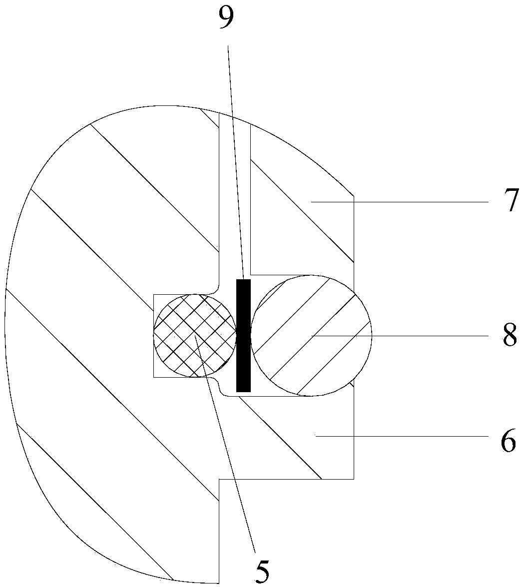
[0029] As a preferred solution of this embodiment, each of the roller collars 4 is provided with an elastic member 5 inside, and all the elastic members 5 are connected to each of the corresponding plunger segments 2. With this structure, ea...


PUM


Abstract

The invention discloses an oil pipe plunger which comprises a fishing head and one or more plunger joints. The ends of every two adjacent plunger joints are hinged to form a plunger joint string; and the fishing head is connected to one ends of the plunger joint strings. The maximum diameter of the fishing head is smaller than or equal to the maximum outer diameter of each plunger joint body. The outer wall of each plunger joint is sleeved with at least one roller shaft ring, and the outer diameters of all the roller shaft rings are larger than the maximum diameter of each plunger joint body. By means of the oil pipe plunger, the roller shaft rings are arranged on the outer wall of the oil pipe plunger, and the roller shaft rings make contact with the inner wall of an oil well pipe, so that original sliding friction between the outer wall of the plunger and the inner wall of the oil pipe is transformed into rolling friction, so that the problems that in the prior art, a plunger repeatedly passes through a bending position when working in an oil well, and sliding friction and abrasion between the plunger and the inner wall of an oil pipe in the position are serious are effectively solved. The oil pipe plunger is simple in structure, convenient to use and long in service life, and the risks of oil and water leaking due to oil pipe abrasion and fracture are reduced.

Description

technical field [0001] The invention relates to an oil extraction equipment, in particular to an oil pipe plunger. Background technique [0002] In oil and gas exploitation, plungers are widely used to move up and down in oil wells to discharge accumulated water in wells. Because directional wells are curved, serious dogleg degrees restrict the ability of plungers to pass through wells. The Chinese patent with publication number CN202531390U discloses a Gas well drainage and gas production plunger, the plunger includes several successively hinged plunger sections, so that the plunger can be bent to pass through the curved part of the tubing in the directional well. [0003] However, the plunger has the following problems. When the plunger passes through the curved part of the oil pipe in the directional well, it always closely fits the inner wall of the oil pipe on the outer side of the bend of the oil pipe, increasing the sliding friction at this place. When the plunger wor...

Claims


Application Information

Patent Timeline
Patent Type & Authority Patents(China)
IPC IPC(8): E21B17/00E21B17/10
CPCE21B17/00E21B17/1042
Inventor 梅宗斌
Owner SICHUAN ANJIE OIL GAS TECHNICAL SERVICE CO LTD
Why Eureka
Try Eureka