
Mechanical drive structure

A mechanical transmission and offset technology, which is applied in the direction of mechanical equipment, transmission devices, portable lifting devices, etc., can solve the problems of system oscillation, radial clearance cannot be eliminated, and system power consumption increase, and achieve the effect of small friction

Active Publication Date: 2017-06-13
SHANGHAI AEROSPACE CONTROL TECH INST
View PDF5 Cites 2 Cited by
  • Summary
  • Abstract
  • Description
  • Claims
  • Application Information

AI Technical Summary

Problems solved by technology

However, since the radial clearance of the bearing itself cannot be eliminated, the existing clearance will easily cause the system to oscillate. Although the interference fit can eliminate the clearance, the bearing and the rocker arm are relatively sliding, and the interference additionally increases the pressure of the rocker arm and the lever. The sliding friction between them will increase the power consumption of the system and slow down the response

Method used


Image

  • Mechanical drive structure
  • Mechanical drive structure
  • Mechanical drive structure

Examples


Embodiment Construction

[0023] According to Figure 1 ~ Figure 7 , A detailed description of the preferred embodiment of the present invention.

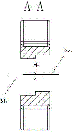
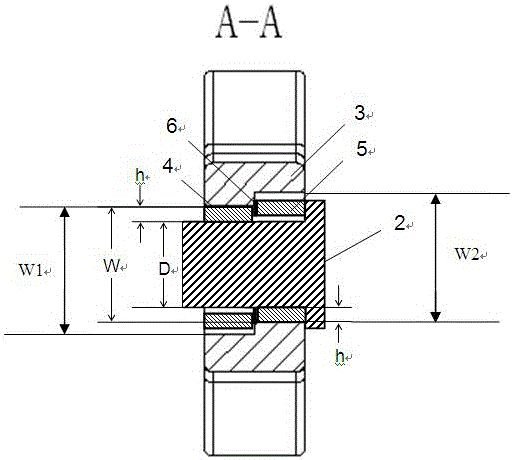
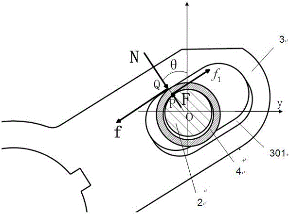
[0024] Such as figure 1 with figure 2 As shown, the present invention provides a mechanical transmission structure, comprising: a rocker arm 3 connecting a ball screw nut 1 (which is threaded to the ball screw 7) and a rudder shaft 8, and a pull rod sleeved on the ball screw nut 1. 2. The anti-backlash ring assembly on and inside the rocker arm 3.

[0025] Such as image 3 As shown, one end of the rocker arm 3 is sleeved on the pull rod 2 of the ball screw nut 1 through the through hole 302, and the other end is connected to the rudder shaft 8. The through hole 302 of the rocker arm 3 is provided with adjacent The first offset track 301 and the second offset track 302, such as Figure 5 As shown, the width W1 of the first offset track 301 is equal to the width W2 of the second offset track 302. Such as Figure 4 As shown, the horizontally symmetrical centerli...


PUM


Abstract

A mechanical drive structure comprises a swing arm and an anti-backlash ring component, the swing arm is connected with a ball screw nut and a rudder shaft, the anti-backlash ring component sleeves a poking rod of the ball screw nut and is positioned in the swing arm, a first offset rail and a second offset rail are adjacently arranged in a through hole of the swing arm, a horizontal symmetric center line of the first offset rail and a horizontal symmetric center line of the second offset rail are not on the same horizontal plane, the anti-backlash ring component comprises a first anti-backlash ring and a second anti-backlash ring which sleeve on the poking rod, the first anti-backlash ring is positioned in the first offset rail, the second anti-backlash ring is positioned in the second offset rail, and the perpendicular distance between the horizontal symmetric center line of the first offset rail and the horizontal symmetric center line of the second offset rail is H. According to the mechanical drive structure, rolling motion between the poking rod of the screw nut and the swing arm is achieved, and matched gap between the poking rod of the screw nut and the swing arm can be adjusted based on decrease of frictional force.

Description

Technical field [0001] The invention relates to a mechanical transmission structure. Background technique [0002] Ball screw pairs are widely used in aircraft servo mechanisms due to their high efficiency, small size, and strong load capacity. The steering gear servo mechanism often cooperates with the ball screw nut through the rocker arm of the rudder shaft, and converts the linear motion of the nut into the swing of the rocker arm and the rudder shaft, and then drives the rudder surface to deflect. [0003] As non-linear factors in the control system, clearance and friction often cause a series of undesirable phenomena such as system response lag and oscillation instability. In previous designs, in order to convert the linear motion of the ball screw nut lever into the circular swing of the rocker arm, joint bearings are often installed between the lever and the rocker arm, or the lever is directly slid in the rocker arm slot. However, because the radial clearance of the bear...

Claims


Application Information

Patent Timeline
Patent Type & Authority Applications(China)
IPC IPC(8): F16H21/54F16H55/24
CPCF16H21/54F16H55/24
Inventor 武晓峰申振丰蒋政韩子晨唐剑超
Owner SHANGHAI AEROSPACE CONTROL TECH INST
Learn More