Annular movable tunnel kiln production line layout process

A tunnel kiln and mobile technology, applied in the field of tunnel kiln, can solve the problems of high failure rate of the power supply side of the sliding contact line, high operation and maintenance costs, cluttered and long lines, etc. , Improve the effect of "correct" air volume

Inactive Publication Date: 2017-06-13
周大林
View PDF5 Cites 1 Cited by
  • Summary
  • Abstract
  • Description
  • Claims
  • Application Information

AI Technical Summary

Problems solved by technology

[0006] The advantage of the present invention is that the central power supply collector is set at the center of the circular track, and with this point as the center of the circle, it supplies power to the mobile platform and the kiln body of the molding workshop repeatedly. The lines using electric wires are also equal, which avoids the messy and long lines caused by uneven line lengths on one side of the kiln body, and overcomes the shortcomings of high failure rate and high operation and maintenance costs of the trolley line collector and power supply side, and It also makes full use of the space at the center of the circular mobile tunnel kiln

Method used


Image

  • Annular movable tunnel kiln production line layout process
  • Annular movable tunnel kiln production line layout process
  • Annular movable tunnel kiln production line layout process

Examples


Embodiment Construction

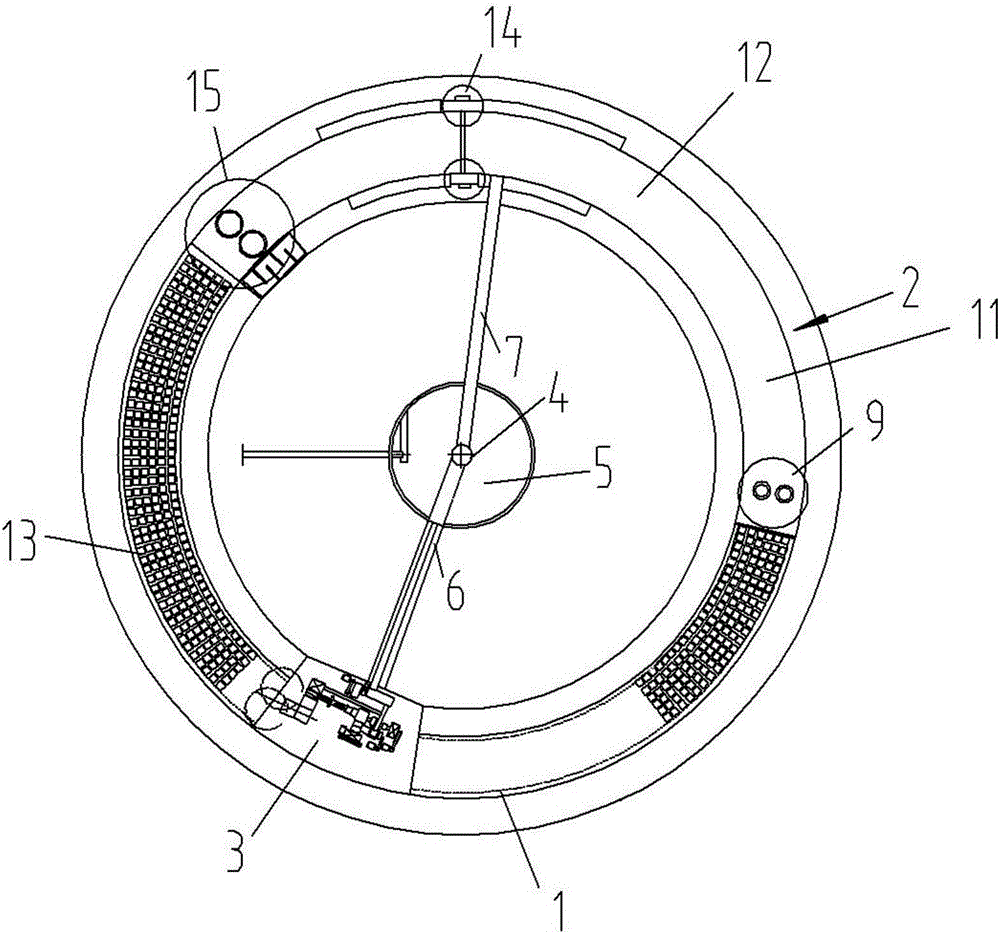
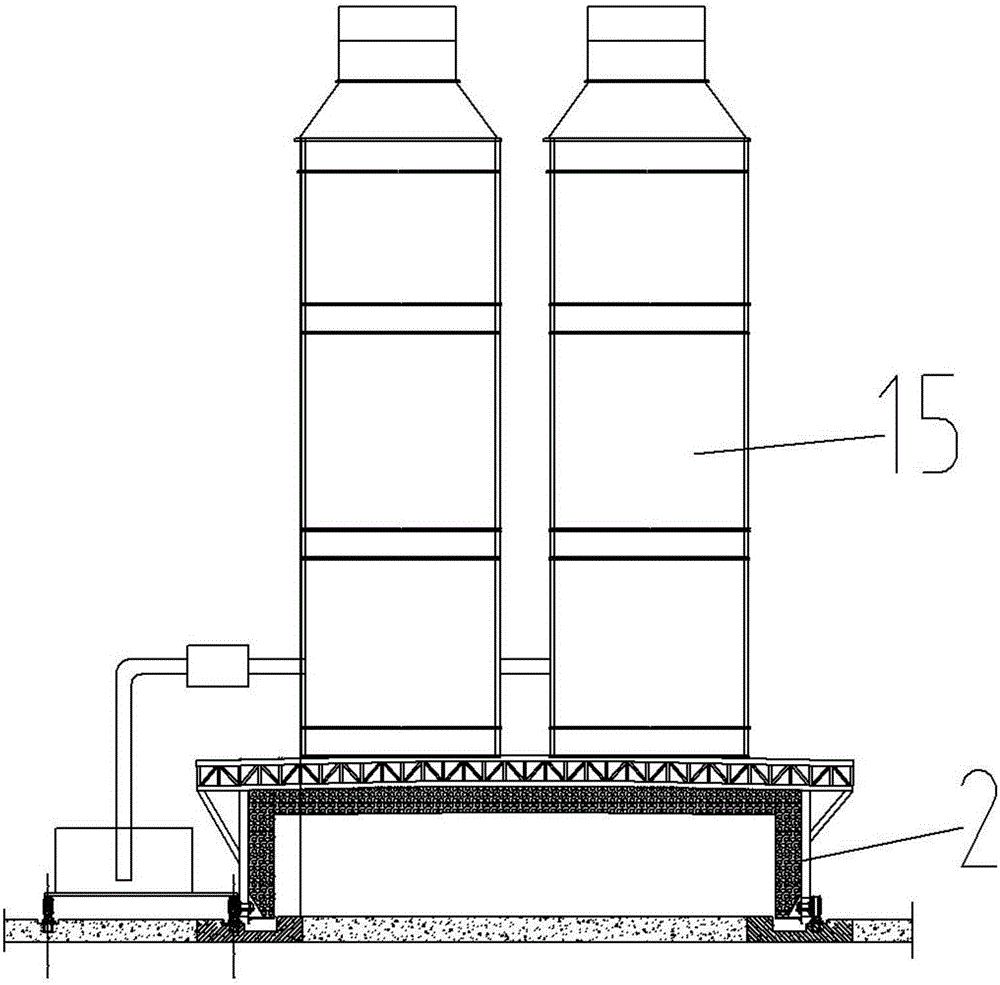
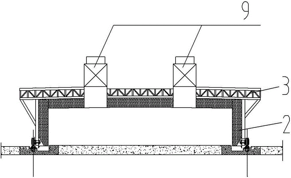
[0020] Below in conjunction with accompanying drawing and specific embodiment the present invention will be described in further detail:

[0021] according to figure 1 , 2 , 3, and 4, the present invention provides a ring-shaped mobile tunnel kiln production line layout process, including the kiln chamber underground material passage, circular track 1, kiln body 2, molding workshop mobile platform 3, and central power supply collector 4 , Production water supply pool 5, the kiln head is equipped with a flue gas purification device set on the top of the kiln and moves with the kiln body, the platform of the purified liquid pool moves with the kiln body 2, the top is arranged with a squall flue and a moisture exhaust fan, and the middle of the kiln is equipped with The side bottom of the smoke hot air passage is arranged, and the forced air oxygen supply device and the tailgate are installed at the tail of the kiln. The central power supply collector 4 is set at the center of ...


PUM


Abstract

The invention relates to a tunnel kiln, in particular to an annular movable tunnel kiln production line layout process. The annular movable tunnel kiln production line layout process adopts a kiln chamber underground material-passing duct, annular track, a kiln body, a forming shop mobile platform, a central power supply and current collecting device and a production water supply pool, wherein the central power supply and current collecting device is arranged at the circle center position of the annular track, the forming shop mobile platform is electrically connected with the central power supply and current collecting device, the kiln body is electrically connected with the central power supply and current collecting device, a kiln head portion is provided with a flue gas purifying device arranged at a kiln top and moving with the kiln body, an agent purifying pool platform moves with the kiln body, a moisture discharging flue and a moisture discharging fan are arranged at the top, a smoke sucking hot air channel is arranged in the middle of the kiln and arranged at the bottom of the side, a kiln tail portion is provided with a forced air feeding and oxygen supply device and a tail door, and an air inlet fan is arranged at the top of the kiln tail portion of the kiln body. By adopting the scheme, the annular movable tunnel kiln production line layout process has the advantages of being low in fault rate, low in maintenance cost and high in yield.

Description

technical field [0001] The invention relates to a tunnel kiln, in particular to a production line layout process of an annular mobile tunnel kiln. Background technique [0002] Previously, the power supply device of the annular mobile tunnel kiln was arranged on one side of the kiln body, and the trolley line was used for power supply. The power supply connection method of this structure has the disadvantages of long line layout, high failure rate and high operation and maintenance costs. Not only that, when the kiln is firing products, air needs to enter the kiln body to provide oxygen for fuel combustion. Currently, there are two ways of air intake at the kiln tail of the fixed tunnel kiln: natural air intake and forced air intake. The natural air intake at the kiln tail is realized by the negative pressure generated by the kiln fan. 2. A large amount of "wrong" air leaks in. There are several kiln cars in the kiln body, and the joints between many kiln cars cannot be air...

Claims


Application Information

Patent Timeline
Patent Type & Authority Applications(China)
IPC IPC(8): F27B9/16F27B9/30F27D7/04
CPCF27B9/16F27B9/3077F27D7/04F27D2007/045
Inventor 周大林
Owner 周大林
Why Eureka
Try Eureka