
Continuous online emission monitoring system

A monitoring system and flue gas technology, applied in measuring devices, instruments, etc., can solve problems such as inability to monitor flue gas, equipment corrosion, and insufficient filtering, and achieve the effects of flexible use, improved accuracy, and powerful software functions.

Pending Publication Date: 2017-06-13
上海宝英光电科技有限公司
View PDF4 Cites 8 Cited by
  • Summary
  • Abstract
  • Description
  • Claims
  • Application Information

AI Technical Summary

Problems solved by technology

[0003] With the enhancement of people's awareness of environmental protection, countries have higher and higher requirements for the limit value of flue gas emission, especially for the pollutant emission of waste incineration plants and power plants. The previous flue gas emission monitoring system can no longer meet the requirements need
For example, the existing flue gas monitoring system has a complex structure, single monitoring data, and cannot conduct comprehensive monitoring of the flue gas; after the gas is sampled from the flue, it is easy to have a temperature difference with the outside air, and moisture will be precipitated, affecting SO 2 and other soluble gases to monitor the concentration, it will also cause serious corrosion to the equipment; in the monitoring process, the filtration is not fine enough, often leaving a lot of dust and water to affect the monitoring effect

Method used


Image

  • Continuous online emission monitoring system
  • Continuous online emission monitoring system

Examples


Embodiment Construction

[0021] In order to make the technical means, creative features, goals and effects achieved by the present invention easy to understand, the present invention will be further described below in conjunction with specific illustrations.

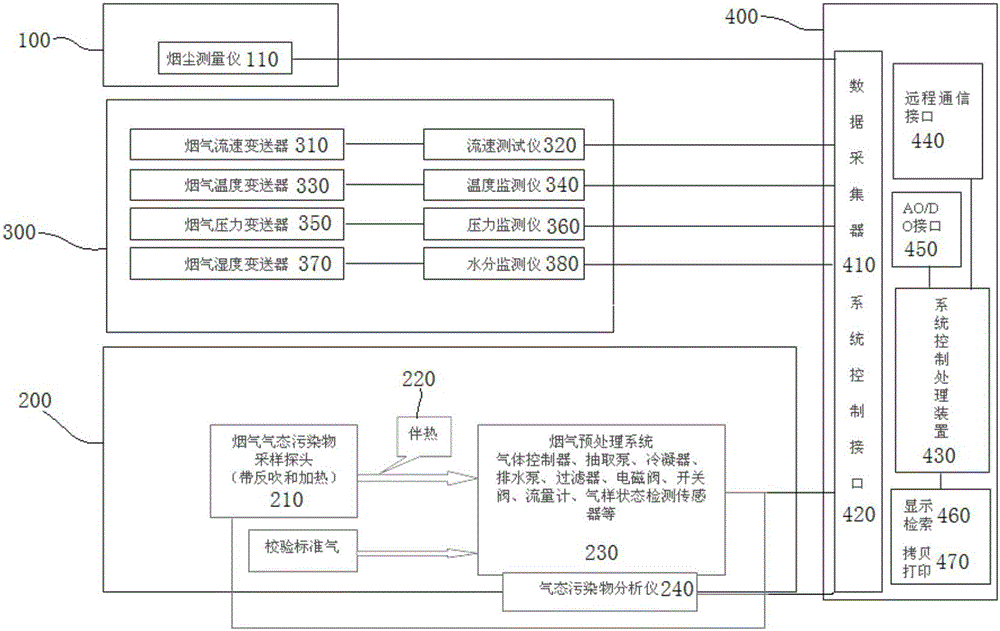
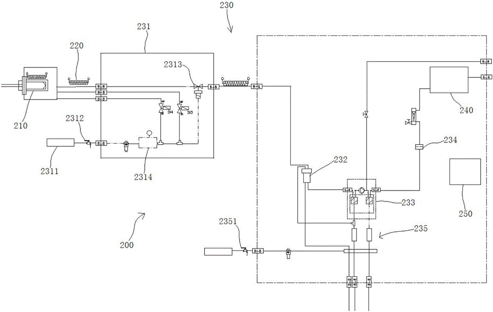
[0022] see Figure 1 to Figure 2 , shown in the figure is a continuous online flue gas monitoring system, including a continuous monitoring subsystem 100 for solid particulate matter, a continuous monitoring subsystem 200 for gaseous pollutants, and a continuous monitoring subsystem 300 for flue gas parameters installed in the chimney or flue, The solid particle continuous monitoring subsystem 100 , the gaseous pollutant continuous monitoring subsystem 200 and the flue gas parameter continuous monitoring subsystem 300 are all connected to the data processing and remote communication system 400 . By monitoring solid particles, gaseous pollutants and flue gas parameters, in conjunction with data processing and remote communication system 400, it h...


PUM

PropertyMeasurementUnit
Outer diameteraaaaaaaaaa

Abstract

The invention discloses a continuous online emission monitoring system which comprises the components of a solid particle continuous monitoring subsystem, a gaseous pollutant continuous monitoring subsystem and an emission parameter continuous monitoring subsystem, wherein the solid particle continuous monitoring subsystem, the gaseous pollutant continuous monitoring subsystem and the emission parameter continuous monitoring subsystem are mounted in a chimney or a flue channel. The solid particle continuous monitoring subsystem, the gaseous pollutant continuous monitoring subsystem and the emission parameter continuous monitoring subsystem are connected with a data processing and remote communication system. The gaseous pollutant continuous monitoring subsystem comprises a sampling probe with a backflow function and a heating function, a trace heating tape, an emission preprocessing system and an infrared gas analyzer, wherein the sampling probe, the trace heating tape, the emission preprocessing system and the infrared gas analyzer are successively connected. Functions such as gas sampling, backflowing, dust filtering and water filtering in the gaseous pollutant continuous monitoring subsystem are controlled through a PLC control system. According to the continuous online emission monitoring system, through monitoring the solid particle, the gaseous pollutant and the emission parameter, by means of remote communication and a data acquisition unit, the continuous online emission monitoring system realizes advantages of remote fault diagnosis, strong software function, high flexibility in use, etc.

Description

technical field [0001] The invention relates to the field, and mainly relates to a continuous online monitoring system for flue gas. Background technique [0002] A device that continuously monitors the concentration and total emission of particulate matter (also called soot) and gaseous pollutants (including sulfur dioxide, nitrogen oxides, etc.) On-line monitoring system", the international general name CEMS (Continuous Emission Monitoring System). The flue gas emission continuous monitoring system can not only be used for emission compliance monitoring and sewage metering, but also can be used for equipment (dust removal, desulfurization, boiler combustion conditions) operating status inspection, fault diagnosis, etc.; thus it is more and more widely used . [0003] With the enhancement of people's awareness of environmental protection, countries have higher and higher requirements for the limit value of flue gas emission, especially for the pollutant emission of waste ...

Claims


Application Information

Patent Timeline
IPC IPC(8): G01D21/02
CPCG01D21/02
Inventor 张磊张红克朱艳黄晓文王昱舸
Owner 上海宝英光电科技有限公司
Learn More