Load-bearing connector test specimen clamp for fatigue test machine

A technology of fatigue testing machine and load-bearing joints, which is applied in the direction of measuring devices, instruments, scientific instruments, etc., can solve the problems of unsatisfactory clamping and accurate detection of multi-directional stretching, and achieve stable clamping, reasonable structural design, The effect of improving accuracy

Active Publication Date: 2017-06-13
SHENYANG SHENGYUAN INSPECTION TECH
View PDF7 Cites 7 Cited by
  • Summary
  • Abstract
  • Description
  • Claims
  • Application Information

AI Technical Summary

Problems solved by technology

[0003] The purpose of the present invention is to provide a load-bearing joint sample fixture for a fatigue testing machine, which solves the problem that the existing load-bearing joint sample fixture cannot meet the requirements of correct clamping and accurate detection of multi-directional tensile and fatigue tests. Its structural design is reasonable to ensure accurate clamping and positioning of load-bearing joint samples, convenient loading and unloading, and stable clamping. It can more realistically simulate the connection of components and the effective transmission and distribution of loads, and significantly improve the multi-directional tensile and Accuracy of fatigue test results

Method used


Image

  • Load-bearing connector test specimen clamp for fatigue test machine
  • Load-bearing connector test specimen clamp for fatigue test machine
  • Load-bearing connector test specimen clamp for fatigue test machine

Examples


Embodiment Construction

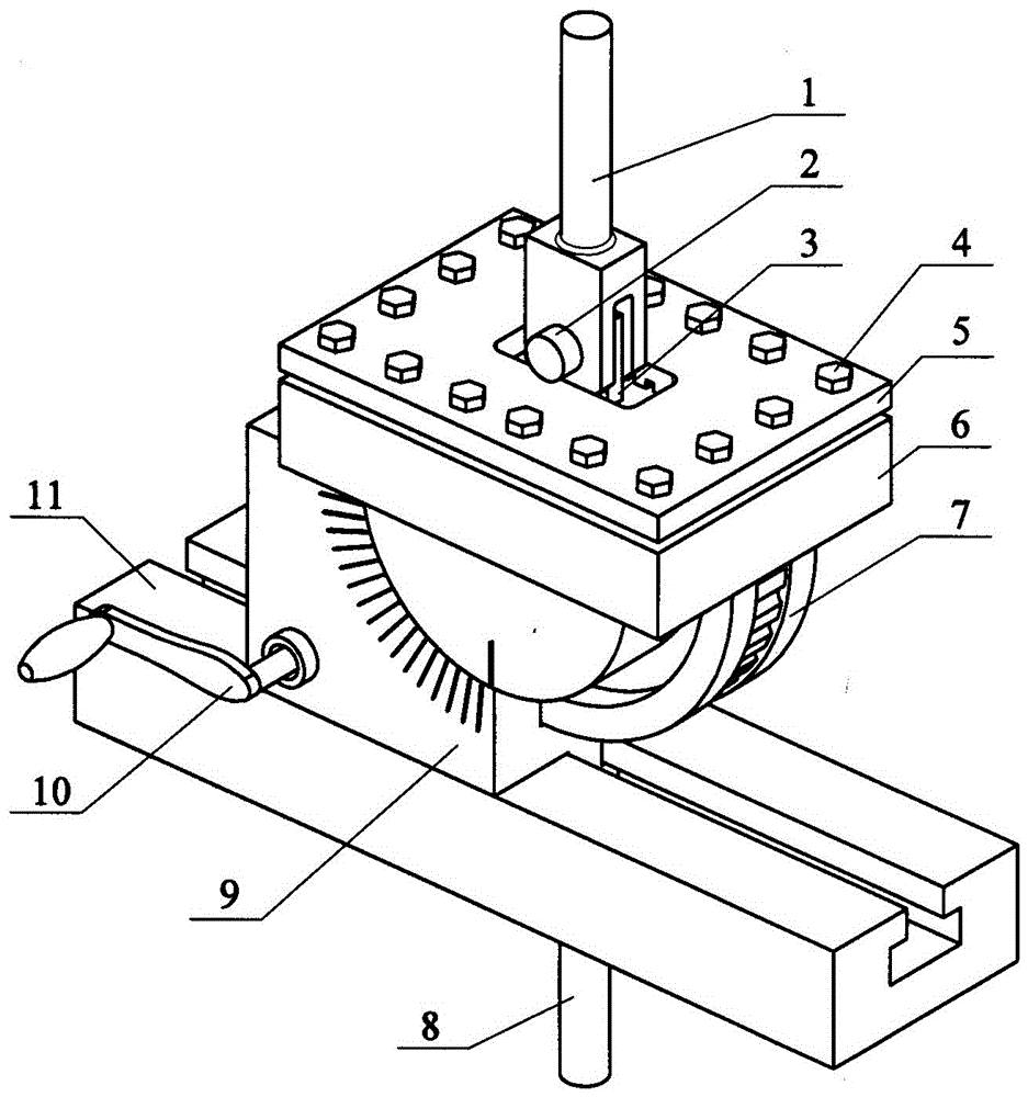
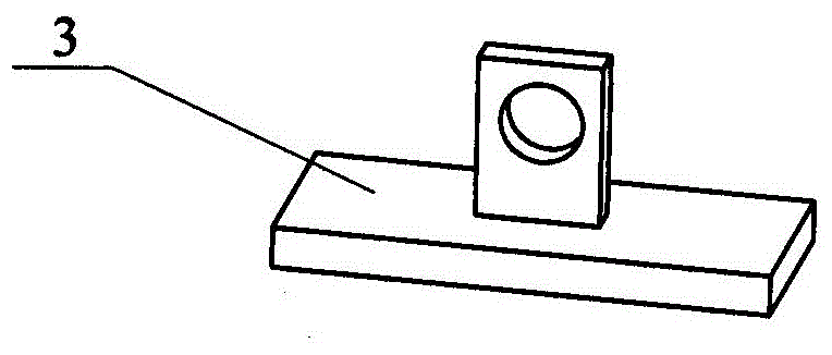
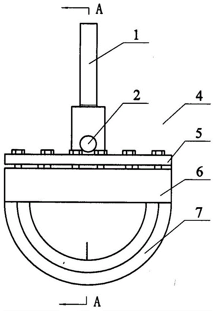
[0022] according to Figure 1-10 The specific structure of the present invention will be described in detail. The load-bearing joint sample fixture for the fatigue testing machine includes a clamping mechanism for clamping the load-bearing joint sample 3 between the upper and lower connecting rods 1 and 8 of the fatigue testing machine, an angle adjustment mechanism and a base 11 and other components. part. Among them, load-bearing joint sample 3 consists of vertical parts and bottoms (such as image 3 shown) constitutes. A stress sensor (not shown in the figure) is attached to the surface of the load-bearing joint sample 3, and the transmission line of the stress sensor is led out through the wire groove on the back of the upper splint 5 and communicated with the computer control equipment.

[0023] The clamping mechanism of clamping load-bearing joint sample 3 is composed of upper and lower splints 5 and 6 with bolt holes around them and fastener bolts 4 and other compone...


PUM


Abstract

The invention provides a load-bearing connector test specimen clamp for a fatigue test machine, and solves the problems that the existing clamp cannot meet the requirements of correct clamping, accurate detection, multi-position stretching and fatigue test and the like. The load-bearing connector test specimen clamp for the fatigue test machine comprises a clamping mechanism, an angle regulating mechanism and a base, wherein the clamping mechanism is assembled between upper and lower connecting rods of the fatigue test machine and is used for clamping and installing a load-bearing connector test specimen. The load-bearing connector test specimen clamp is mainly characterized in that the clamping mechanism consists of upper and lower clamping plates and a fastening element screw bolt; screw bolt holes are formed in the peripheries of the upper and lower clamping plates; the load-bearing connector test specimen is hinged to the upper connecting rod through a pin shaft; the base is assembled with a fatigue test machine platform through the lower connecting rod; the angle regulating mechanism consists of a box body provided with a crank transmission mechanism and a semicircular worm wheel block assembled in a box body rotating groove. The load-bearing connector test specimen clamp has the advantages that the structural design is reasonable; the clamping and positioning accuracy of the load-bearing connector test specimen is ensured; the mounting and the dismounting are convenient; the clamping is stable; the connection of components and the effective transmission and distribution of the load can be really simulated; the multi-position stretching and fatigue test result accuracy can be obviously improved.

Description

technical field [0001] The invention relates to a special tool for clamping a load-bearing joint sample, in particular to a load-bearing joint sample clamp for a fatigue testing machine that meets the requirements for multi-directional loading experiments on the edge of a clamped sample hole. Background technique [0002] In the aircraft structure, connection joints are used to realize the connection between different components and the transmission and distribution of loads. Because the fastener hole edge of the load-bearing joint is the place where the structural stress concentration is the most serious, and the stress concentration is the place that leads to the reduction of structural strength and Therefore, it is necessary to conduct multi-directional loading mechanical performance tests on load-bearing joint samples. The overall stress characteristics of the load-bearing joint and the mechanical properties such as the stress distribution characteristics at the edge of ...

Claims


Application Information

Patent Timeline
Patent Type & Authority Applications(China)
IPC IPC(8): G01N3/04
CPCG01N3/04G01N2203/0482G01N2203/0073G01N2203/0423G01N2203/0405Y02E30/30
Inventor 许良周松马少华李鹤王宏伟
Owner SHENYANG SHENGYUAN INSPECTION TECH
Why Eureka
Try Eureka