Wind power blade fatigue loading test device

A technology of fatigue loading and testing equipment, which is applied in the direction of measuring equipment, testing material strength by applying repetitive force/pulsation force, testing mechanical parts, etc., and can solve problems such as poor assembly process, low efficiency, and high energy consumption

Inactive Publication Date: 2017-06-13
SHANDONG UNIV OF TECH
View PDF4 Cites 7 Cited by
  • Summary
  • Abstract
  • Description
  • Claims
  • Application Information

AI Technical Summary

Problems solved by technology

Among them, the eccentric mass fatigue loading test device is widely used, and the eccentric mass fatigue loading test device has a simple structure and is easy to install, but only the vertical component does useful work during the rotation of the eccentric mass, and the energy utilization rate is low; the hydraulic inertia The fatigue loading test device needs a set of electro-hydraulic servo system control with complex structure, which has high requirements, high energy consumption and low efficiency. The fatigue life of the blade will affect the reliability of the fatigue loading test of the blade; the electric servo fatigue loading test device uses the servo motor as the power source to carry out the fatigue loading test on the wind turbine blade. The control system of this loading device is relatively simple, the loading reliability is high, and the energy utilization High rate, in line with the trend of green development, but the traditional electric servo fatigue loading test device has poor assembly process, low lead screw life and difficult adjustment of counterweight

Method used


Image

  • Wind power blade fatigue loading test device
  • Wind power blade fatigue loading test device
  • Wind power blade fatigue loading test device

Examples


Embodiment Construction

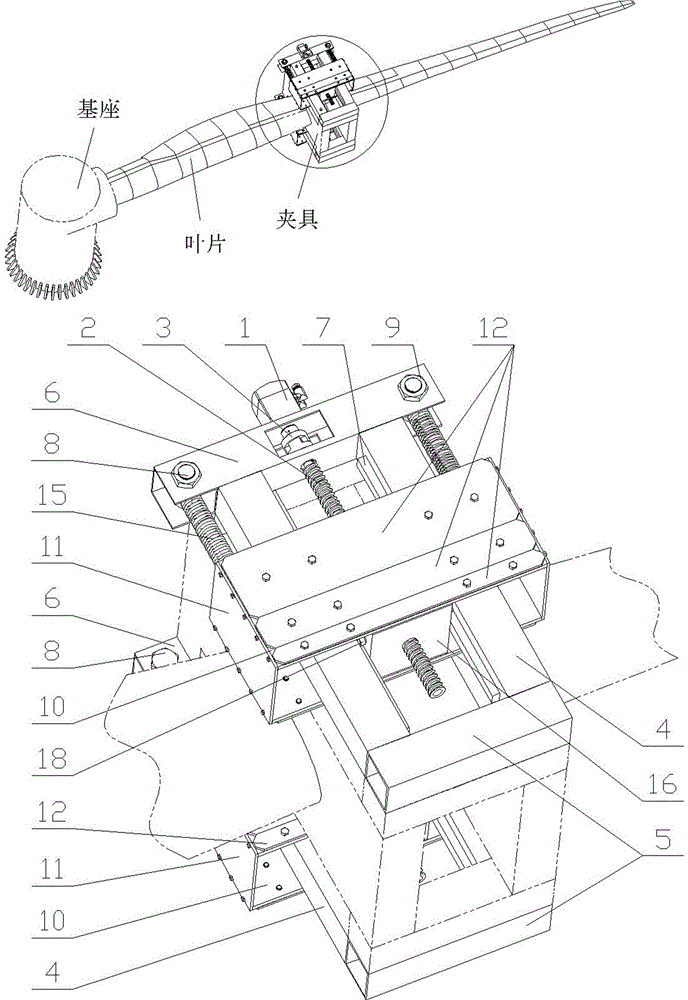
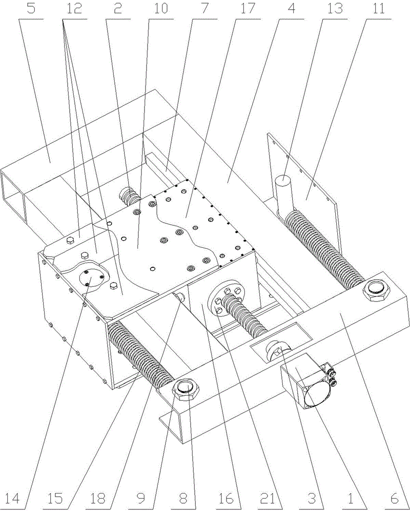
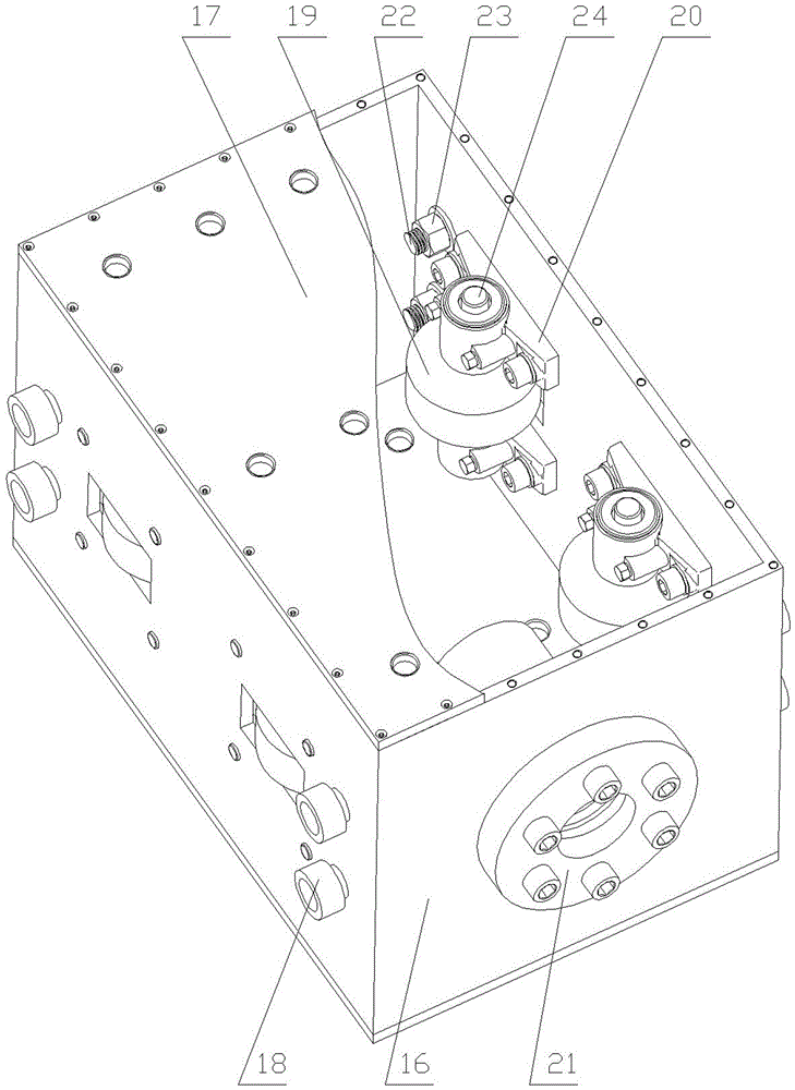
[0024] 1. Servo motor 2, lead screw 3, coupling 4, pillar 5, beam I 6, beam II 7, guide rail 8, pin shaft I 9, nut I 10, mounting plate 11, side plate 12, counterweight 13, Pin shaft II 14, baffle plate 15, spring 16, box body 17, cover plate 18, guide wheel I 19, guide wheel II 20, support 21, screw nut 22, pin shaft III 23, nut II 24, pin shaft IV.

[0025] exist Figure 1-Figure 3 In the shown embodiment: on the basis of the prior art, the present invention has equal lengths and two pillars 4 made of square tubes are located in the same plane, and one end is fixedly connected by a beam I5 made of a square tube, and the length of the beam I5 is equal to After the connection, the distance between the outer sides of the two pillars 4, and the other end is fixedly connected by a beam II6 made of a square tube. The two ends of the beam II6 protruding from the outer sides of the two pillars 4 are provided with axes perpendicular to where the two pillars 4 are located. In the thr...


PUM


Abstract

The invention provides a wind power blade fatigue loading test device and provides a counterweight distribution method for the device. A servo motor is mounted on the device body. A screw rod is connected to an output shaft of the servo motor through a coupler. A protection box of a counterweight block is fastened to a sliding block. The device is characterized in that the centers of the front and rear side walls of the box body of the sliding block are provided with round holes having different diameters, a nut is installed in the round hole having the larger diameter, a guide wheel I and a guide wheel II are respectively mounted on the left and right side walls of the box body through a pin III and a pin IV, the sliding block sleeves the screw through the nut, the guide wheel I and the guide wheel II contact with a guide rail to provide a guide support force to the sliding block, the fatigue loading device utilizes a hollow ball screw to carry out transmission, and the mass of a group of the counterweight blocks is distributed according to geometric progression having a common ratio of 2. The device has high test reliability, is easy to clamp, can simply, conveniently and accurately adjust and install the counterweight blocks based on the premise of satisfying counterweight requirements and saves manpower and material resources.

Description

technical field [0001] The invention provides a wind power blade fatigue loading test device, which is mainly used for the fatigue test of the wind power blade. Background technique [0002] The main function of the wind turbine blade fatigue loading test device is to perform fatigue loading tests on wind turbine blades. At present, the fatigue loading test devices used mainly include the eccentric mass block fatigue loading test device, the hydraulic inertia fatigue loading test device and the electric servo fatigue loading test device. Among them, the eccentric mass fatigue loading test device is widely used, and the eccentric mass fatigue loading test device has a simple structure and is easy to install, but only the vertical component force does useful work during the rotation of the eccentric mass, and the energy utilization rate is low; the hydraulic inertia The fatigue loading test device needs a set of electro-hydraulic servo system control with complex structure, w...

Claims


Application Information

Patent Timeline
Patent Type & Authority Applications(China)
IPC IPC(8): G01N3/38G01M13/00
CPCG01M13/00G01N3/38G01N2203/0005G01N2203/005G01N2203/0073
Inventor 黄雪梅张磊安陶黎明袁光明魏修亭刘卫生
Owner SHANDONG UNIV OF TECH
Why Eureka
Try Eureka