Cloud measuring radar

A cloud-measuring radar and radar technology, applied in the field of cloud-measuring radar, can solve the problems of increasing the operating burden of the vehicle, requiring a large area, and complicated installation, etc., to achieve convenient assembly, reduce the weight of the radar, and facilitate troubleshooting and maintenance Enhanced effect

Active Publication Date: 2017-06-13
ANHUI SUN CREATE ELECTRONICS
View PDF5 Cites 8 Cited by
  • Summary
  • Abstract
  • Description
  • Claims
  • Application Information

AI Technical Summary

Problems solved by technology

The current problems of cloud measuring radars are: on the one hand, traditional cloud measuring radars adopt mechanical processing or welding structures as a whole. Although they are stable and reliable, their structures are bulky and require a lot of space. When combined with vehicles, the load will also increase. operating burden
On the other hand, there are many structural parts of the traditional cloud measuring radar, which makes the installation extremely complicated; once faced with troubleshooting or periodic maintenance, it is often necessary to disassemble and assemble the entire radar, which is extremely time-consuming and laborious
In addition, the antenna feeder part and other subsystems in the existing cloud measuring radar are independent units, only the power supply and servo actuators are integrated with the antenna feeder system, while other components such as monitoring components and signal processing components are located in the control cabinet In this way, it is required to connect the indoor unit and the outdoor unit with cables, and there will be a lot of inconvenience in the actual installation and use process.

Method used


Image

  • Cloud measuring radar
  • Cloud measuring radar
  • Cloud measuring radar

Examples


Embodiment Construction

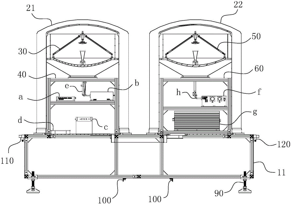
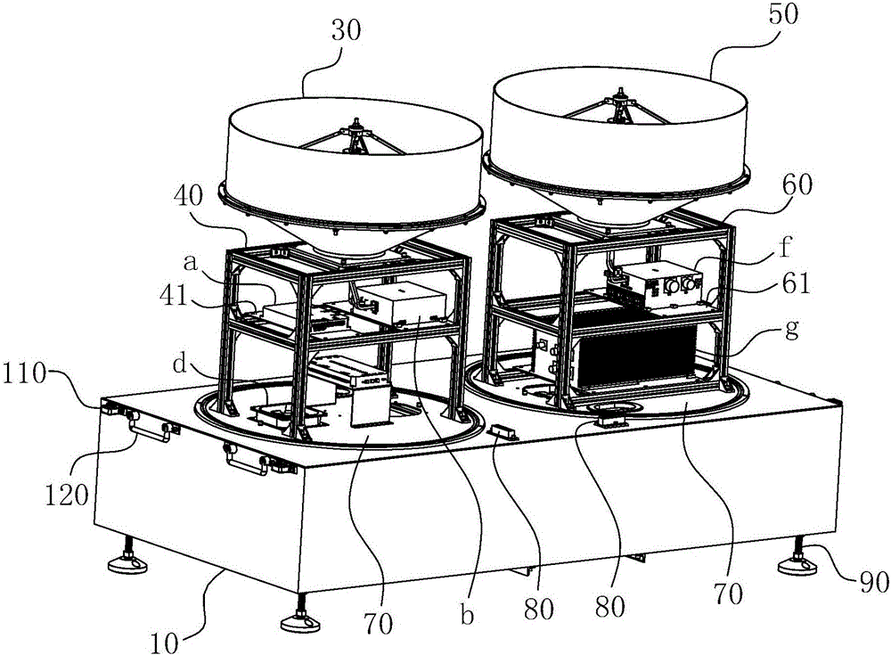
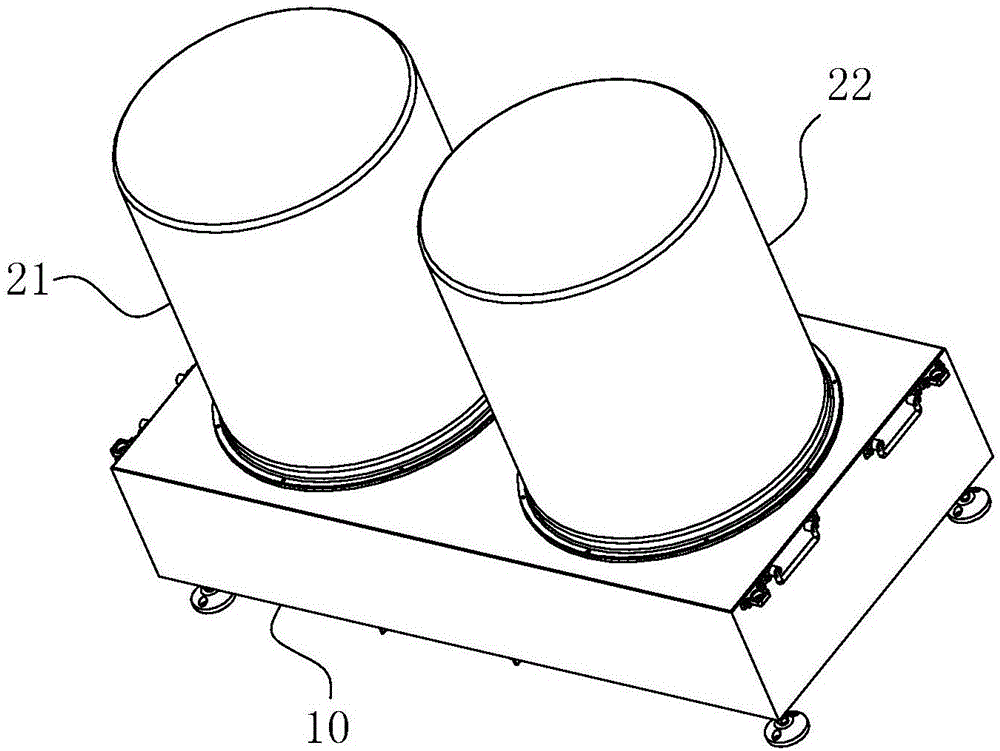
[0037] For ease of understanding, combined here Figure 1-8 Concrete structure of the present invention and working process are described further as follows:

[0038] The specific structure of the present invention is as Figure 1-8 As shown, the whole machine is mainly composed of four parts: one is the bottom profile frame 11, the left profile frame 40 and the right profile frame 60 formed by assembling the profiles through special connectors; the other is forming the receiving antenna 30 and the transmitting antenna The Cassegrain antenna of 50; the third is the first radome 21 and the second radome 22 that are arranged on the receiving antenna 30, the transmitting antenna 50 and the corresponding profile frame; the fourth is the electronic radome arranged in the corresponding profile frame equipment. The main frame body 10 has a cuboid shape, and the first radome 21 and the second radome 22 are arranged on the top surface of the main frame body 10 so as to be parallel to...


PUM


Abstract

The invention belongs to the technical field of electronic communications of radars, and particularly relates to a cloud measuring radar. The radar comprises a main frame body, a first antenna housing and a second antenna housing, wherein the main frame body comprises a bottom sectional-material frame and a skin; the first antenna housing and the second antenna housing both form sealing fit with the top end surface of the main frame body; a receiving antenna and a left sectional-material frame are held in a housing cavity of the first antenna housing; a monitoring component and a receiver are arranged on a horizontal transverse baffle plate at the left sectional-material frame; a signal processing component and a fan are arranged at the top end surface of the main frame body just under the horizontal transverse baffle plate; a transmitting antenna and a right sectional-material frame are held in a housing cavity of the second antenna housing; a transmitter is arranged on a horizontal supporting plate at the right sectional-material frame; a power supply component is arranged at the top end surface of the main frame body just under the horizontal supporting plate. The cloud measuring radar has the advantages of being concise and portable in structure, convenient and quick to maintain, short in making period and low in cost; the batch production can be realized.

Description

technical field [0001] The invention belongs to the field of radar electronic communication, and in particular relates to a cloud measuring radar. Background technique [0002] The energy distribution and water cycle in the atmosphere are the main factors affecting global climate change, and clouds play a non-negligible role in the above process. Cloud radar is an effective means to obtain cloud characteristic parameters through active measurement technology. It emits a signal in a fixed form, uses a detector to detect the echo signal, and then extracts effective information, and finally inverts the required cloud information. The current problems of cloud measuring radars are: on the one hand, traditional cloud measuring radars adopt mechanical processing or welding structures as a whole. Although they are stable and reliable, their structures are bulky and require a lot of space. When combined with vehicles, the load will also increase. operating burden. On the other ha...

Claims


Application Information

Patent Timeline
Patent Type & Authority Applications(China)
IPC IPC(8): G01S13/95G01S7/02
CPCG01S7/02G01S13/951Y02A90/10
Inventor 丁飞王家明苏涛刘鲁军吴良姜炎周雷
Owner ANHUI SUN CREATE ELECTRONICS
Why Eureka
Try Eureka