Automatic charging apparatus and charging control method for unmanned aerial vehicle

A technology of autonomous charging and control methods, applied in the direction of circuit devices, battery circuit devices, collectors, etc., can solve the problems of poor battery life, high inspection costs, and manual work, so as to avoid manual assistance, improve efficiency, The effect of expanding the scope of the area

Inactive Publication Date: 2017-06-13
BEIJING RES INST OF MECHANICAL & ELECTRICAL TECH
View PDF3 Cites 3 Cited by
  • Summary
  • Abstract
  • Description
  • Claims
  • Application Information

AI Technical Summary

Problems solved by technology

The use of helicopter inspections can not be affected by the geographical environment and improves the efficiency of checking line faults. However, the degree of automation of helicopter inspection technology is not high, manual work is still required, and inspection costs are high, so this technology is difficult to obtain. Widespread use
The inspection technology based on drones makes up for the shortcomings of helicopters, but its battery life is very poor, and it cannot carry out long-distance and long-term inspections. In this way, it is still impossible to complete power in remote mountainous areas or places with harsh environments. Inspection work, resulting in many power failures

Method used


Image

  • Automatic charging apparatus and charging control method for unmanned aerial vehicle
  • Automatic charging apparatus and charging control method for unmanned aerial vehicle
  • Automatic charging apparatus and charging control method for unmanned aerial vehicle

Examples


Embodiment 1

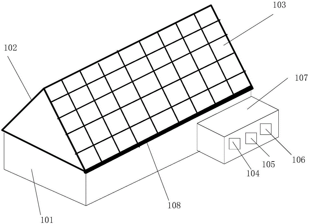
[0021] refer to figure 1 , the present embodiment provides a drone autonomous charging device, including:

[0022] Housing 101, the inside of the housing 101 is used to park the drone;

[0023] The first solar panel 102 and the second solar panel 103 arranged on the top of the housing 101 are used to convert solar energy into electrical energy;

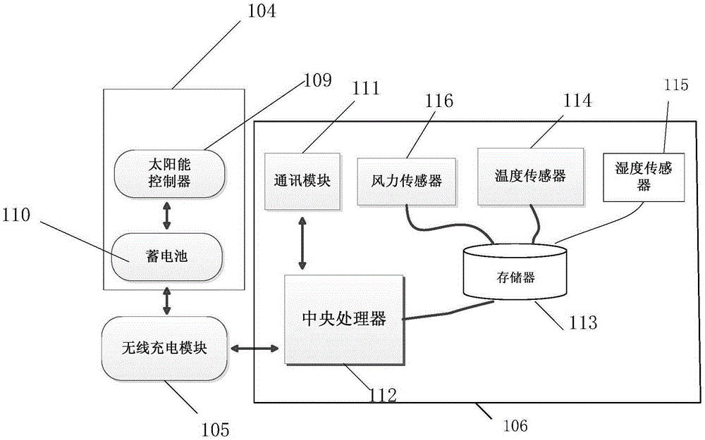
[0024] An energy storage module 104, configured to store the converted electric energy;

[0025] The wireless charging module 105 is connected with the energy storage module 104 for charging the drone;

[0026] The control module 106 is configured to obtain charging request information sent by the drone, and generate a charging control signal according to the charging request information, and the charging control signal is used to control the wireless charging module to charge the drone.

[0027] The UAV autonomous charging device provided by this embodiment makes up for the disadvantage that UAVs cannot inspect remote areas due to...

Embodiment 2

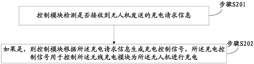
[0044] refer to image 3 , the present embodiment provides a method for controlling the autonomous charging of the UAV, using the UAV autonomous charging device described in Embodiment 1 to charge the UAV, the method includes:

[0045] Step S201, the control module detects whether the charging request information sent by the drone is received;

[0046] Step S202, if yes, the control module generates a charging control signal according to the charging request information, and the charging control signal is used to control the wireless charging module to charge the drone.

[0047] Please refer to Embodiment 1 for the specific structure and working principle of the drone's autonomous charging device, and details will not be repeated here.

[0048] Further, one side of the first solar cell panel and the second solar cell panel are docked, and the other side is respectively fixedly connected to the housing, and the drone autonomous charging device also includes an opening and clos...


PUM


Abstract

The invention provides an automatic charging apparatus and charging control method for an unmanned aerial vehicle. The automatic charging apparatus comprises a shell, a first solar battery panel and a second solar battery panel, an energy storage module, a wireless charging module, and a control module, wherein the unmanned aerial vehicle is placed in the interior of the shell; the first solar battery panel and the second solar battery panel are arranged on the top of the shell and used for converting solar energy into electric energy; the energy storage module is used for storing the converted electric energy; the wireless charging module is connected with the energy storage module and used for charging the unmanned aerial vehicle; and the control module is used for obtaining charging request information sent from the unmanned aerial vehicle and generating a charging control signal according to the charging request information; and the charging control signal is used for controlling the wireless charging module to charge the unmanned aerial vehicle. By adoption of the apparatus and the method, guarantee is provided for electric power inspection of the unmanned aerial vehicle.

Description

technical field [0001] The invention relates to the technical field of power grid intelligent inspection, in particular to an autonomous charging device and a charging control method for an unmanned aerial vehicle. Background technique [0002] With the continuous improvement of national infrastructure, the area covered by the power grid is increasing, which puts forward higher requirements for power grid inspection. Transmission and distribution lines must not only bear high-voltage power loads, but also withstand external mechanical loads for a long time, as well as damage from nature and external forces such as earthquakes, thunderstorms, and strong winds. If the ability and efficiency of power line inspections cannot be improved, the power system will Safety cannot be guaranteed. However, the traditional manual inspection method has obvious defects such as many human factors, high management costs, and low efficiency, and is no longer suitable for large-scale power grid...

Claims


Application Information

Patent Timeline
IPC IPC(8): H02J7/00H02J7/35
Inventor 黄晗邢立伟王金慧
Owner BEIJING RES INST OF MECHANICAL & ELECTRICAL TECH
Why Eureka
Try Eureka