Super high speed permanent magnet motor hollow rotor cooling structure

A permanent magnet motor and hollow rotor technology, applied in cooling/ventilation devices, electrical components, electromechanical devices, etc., can solve the problems of unsatisfactory cooling effect and small application range, achieve low cooling cost, improve cooling efficiency, and improve cooling structure simple effect

Active Publication Date: 2017-06-13
SHENYANG INST OF ENG
View PDF17 Cites 22 Cited by
  • Summary
  • Abstract
  • Description
  • Claims
  • Application Information

AI Technical Summary

Problems solved by technology

[0007] For the hydrogen-cooled structure, it is divided into surface cooling and internal cooling. Although surface cooling can reduce the surface temperature of the winding, the temperature in the insulating layer hardly changes, so the cooling effect is not ideal; the internal cooling is through the solid copper wire The hollow steel pipe is clamped in the middle, and the hydrogen gas flows through the steel pipe, and then the heat in the copper wire is extracted, but the internal cooling is only suitable for large generators, so the scope of application is small

Method used


Image

  • Super high speed permanent magnet motor hollow rotor cooling structure
  • Super high speed permanent magnet motor hollow rotor cooling structure
  • Super high speed permanent magnet motor hollow rotor cooling structure

Examples


Embodiment Construction

[0024] The present invention will be further described in detail below in conjunction with the accompanying drawings and specific embodiments.

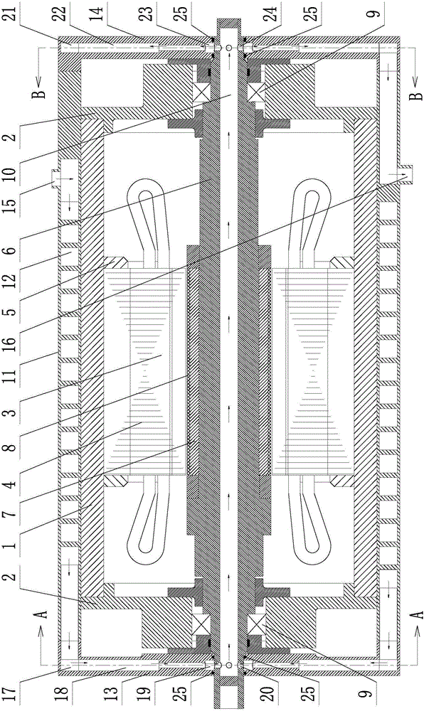
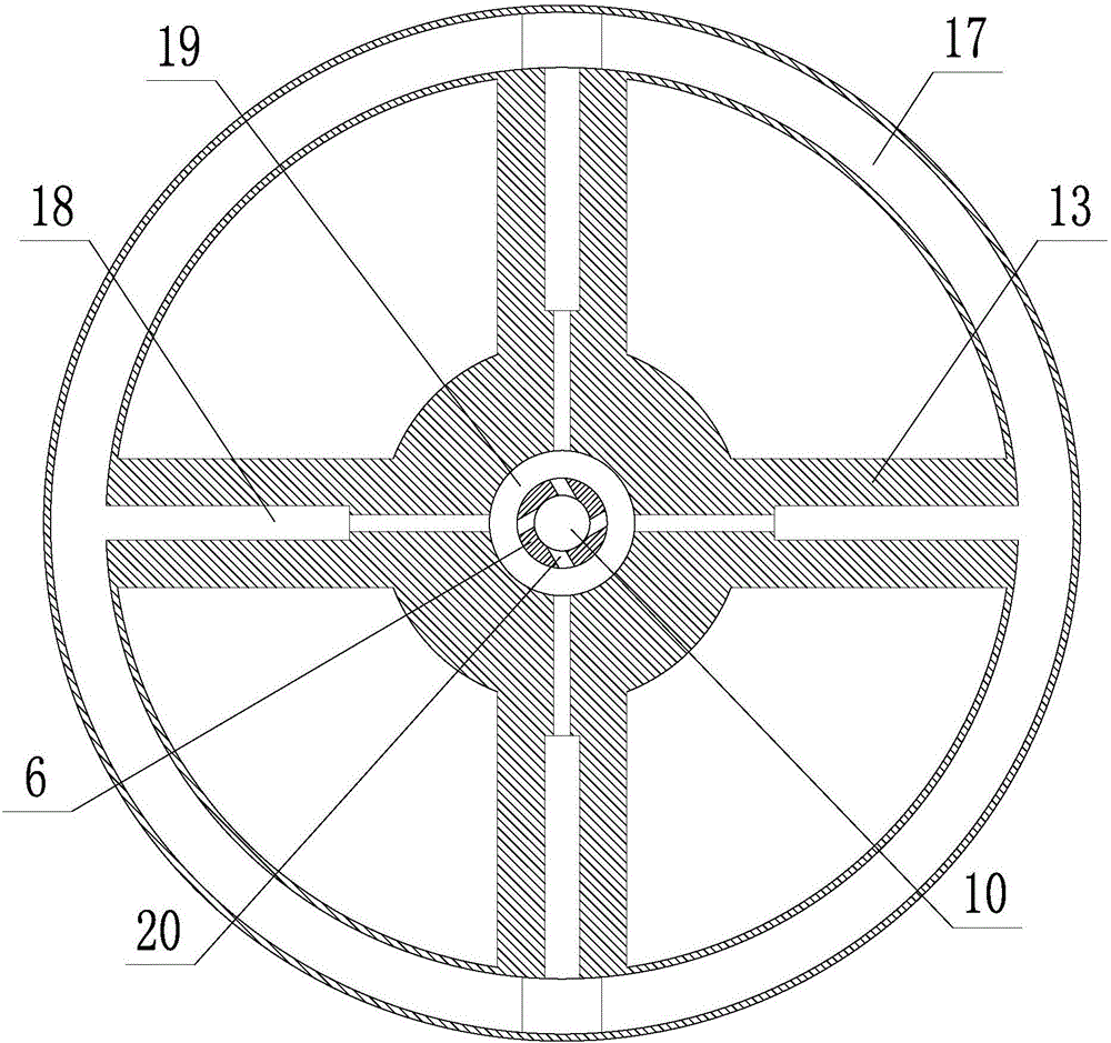
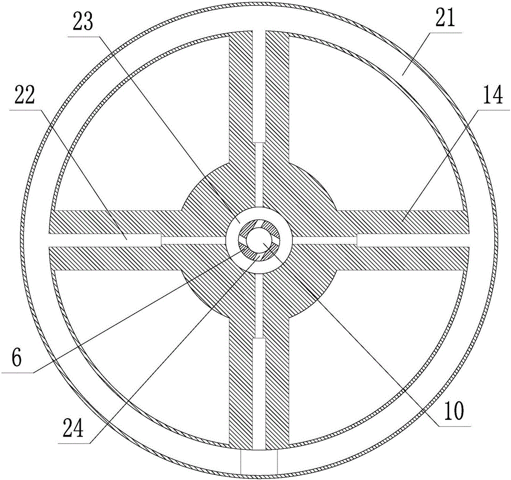
[0025] Such as Figure 1~3 As shown, a hollow rotor cooling structure of an ultra-high-speed permanent magnet motor includes a casing 1, an end cover 2, a stator and a rotor, the stator includes a stator core 3, a stator winding 4 and a stator pressure plate 5, and the rotor includes a rotating shaft 6 , a permanent magnet 7 and a carbon fiber sheath 8; the stator core 3 is fixedly arranged on the inner surface of the casing 1, the stator winding 4 is fixedly arranged on the stator core 3, and the stator pressure plate 5 is fixedly arranged on both ends of the stator core 3; The end cover 2 is fixedly arranged at both ends of the casing 1, the rotating shaft 6 is connected to the end cover 2 through a bearing 9, the permanent magnet 7 is fixedly arranged on the surface of the rotating shaft 6, and the carbon fiber sheath 8 is set on t...


PUM


Abstract

The invention provides a super high speed permanent magnet motor hollow rotor cooling structure. A rotation shaft adopts a hollow structure, and a center hole channel of the rotation shaft is a rotor axial cooling waterway; the outside of a machine case is provided with a cooling water jacket in a sleeved mode, and the inside of the cooling water jacket is provided with a stator circumferential spiral cooling waterway; one end of the cooling water jacket is provided with an inlet water cooling end cover, and the inlet water cooling end cover is installed at one end of the rotation shaft in a sleeving mode; the other end of the cooling water jacket is provided with an outlet water cooling end cover, and the outlet water cooling end cover is installed at the other end of the rotation shaft in a sleeving mode; the stator circumferential spiral cooling waterway is communicated with the outlet water cooling end cover through the inlet water cooling end cover and the rotor axial cooling waterway in sequence; the cooling water jacket is provided with a cooling water inlet and a cooling water outlet, the cooling water inlet is communicated with a water inlet end of the rotor axial cooling waterway, and the cooling water outlet is communicated with a water outlet end of the outlet water cooling end cover. The super high speed permanent magnet motor hollow rotor cooling structure achieves stator cooling and meets rotor cooling at the same time for the first time, effectively improves the cooling efficiency, and has the advantages of being simple in cooling structure, low in cooling cost, free of wind abrasion and long in motor safe operation service life.

Description

technical field [0001] The invention belongs to the technical field of ultra-high-speed permanent magnet motors, in particular to a cooling structure for a hollow rotor of an ultra-high-speed permanent magnet motor. Background technique [0002] The ultra-high-speed permanent magnet motor has the characteristics of simple structure, high force-energy density, no excitation loss and high efficiency, and can be directly connected with the workload to achieve direct drive. It is used in high-speed grinding machines, air circulation refrigeration systems, energy storage flywheels, high-speed Compressors, blowers, aerospace and other technical fields have broad application prospects. [0003] However, under high-speed and high-frequency conditions, ultra-high-speed permanent magnet motors will significantly increase stator loss, rotor eddy current loss, and wind wear due to high fundamental frequency. Due to the difficulty in heat dissipation of ultra-high-speed permanent magnet ...

Claims


Application Information

Patent Timeline
Patent Type & Authority Applications(China)
IPC IPC(8): H02K9/19H02K5/20
CPCH02K5/20H02K9/19Y02T10/64
Inventor 王天煜温福强王大朋王凤翔白斌谭越
Owner SHENYANG INST OF ENG
Why Eureka
Try Eureka