Environment-friendly anti-corrosion large grounding grid with adjustable grounding impedance and construction method

A technology of grounding impedance and grounding grid, applied in the direction of connection, connection contact material, electrical components, etc., can solve the problems of difficult grounding impedance, inability to operate safely, erosion, etc., to prolong safe operation life, reduce soil resistivity, and resist Corrosion life extension effect

Pending Publication Date: 2021-03-30
高政
View PDF1 Cites 1 Cited by
  • Summary
  • Abstract
  • Description
  • Claims
  • Application Information

AI Technical Summary

Problems solved by technology

Electrochemical erosion by harmful substances in the soil, causing severe corrosion and disconnection
After iron oxide and copper oxide are produced, the grounding resistance increases and cannot be restored to the safe operating value
[0004] It is very difficult to lay measuring wires due to the damage of young crops and urban buildings when measuring large-scale grounding grids according to regulations. The measured grounding resistance and conduction value cannot correctly judge the electrical integrity, safety and reliability of the grounding grid.
[0005] It is very difficult to reduce the grounding impedance for large grounding grids in areas with high soil resistivity
Unable to meet the technical requirements of conducting the grounding short-circuit current of the power system and releasing the lightning current

Method used


Image

  • Environment-friendly anti-corrosion large grounding grid with adjustable grounding impedance and construction method
  • Environment-friendly anti-corrosion large grounding grid with adjustable grounding impedance and construction method
  • Environment-friendly anti-corrosion large grounding grid with adjustable grounding impedance and construction method

Examples


Embodiment Construction

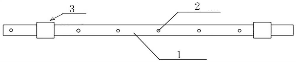
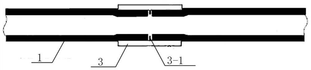
[0045] as attached Figures 1 to 10 Shown is an embodiment of an environment-friendly, anti-corrosion, and resistance-reducing large-scale grounding grid in the present invention. A release hole 2 capable of releasing a non-toxic and harmless liquid drag-reducing material.

[0046] The large-scale grounding grid includes a circle of closed-loop tubular outer edge equalizing busbars buried in the outermost edge of the power plant, substation, petroleum, chemical plant, and dangerous goods storage area, and a grounding grid buried in the equipment area The main body, the main body of the grounding grid includes the tubular equalizing busbars buried between each row of production equipment in the equipment area, as well as the protective grounding wires of high-voltage equipment and production equipment. connected;

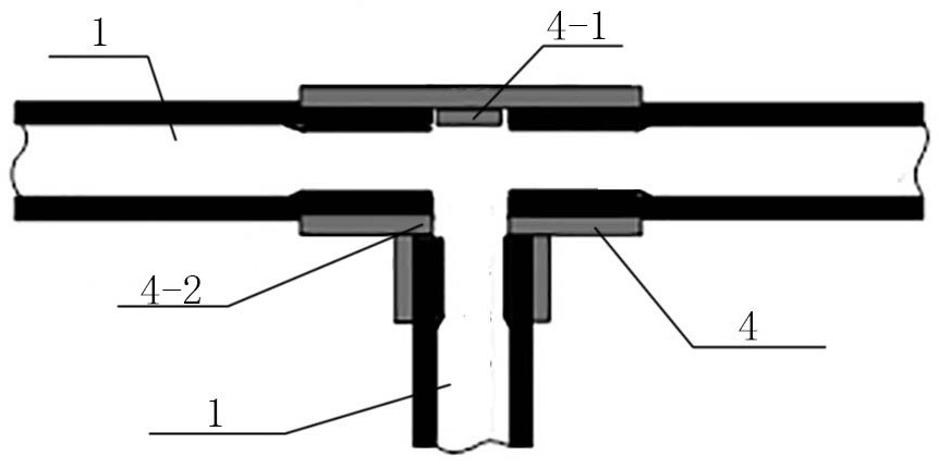
[0047] Above the ground of the grounding network in each equipment area, install a steel pipe vertically connected with the equalizing busbar as the injection hole...


PUM


Abstract

The invention relates to an environment-friendly anti-corrosion large grounding grid with adjustable grounding impedance. A voltage-sharing bus is made of a seamless steel tube of which the inner walland the outer wall are subjected to conductive and antiseptic treatment, and release holes are uniformly distributed in the tube; the grounding grid comprises a circle of outer edge voltage-sharing bus buried at the outermost edge of a whole area and a grounding grid main body buried in an device area, the grounding grid main body comprises a tubular voltage-sharing bus and a grounding wire whichare buried in the device area, and an outer edge voltage-sharing bus and a grounding grid main body voltage-sharing bus are communicated with each other; a steel pipe vertically communicated with thevoltage-sharing buses is mounted above the ground of each device area to serve as an injection hole, the top end of each injection hole is of a sealed structure, and a grounding electrode which is vertically communicated with the tubular voltage-sharing bus and is downwards inserted into the ground is arranged on the tubular voltage-sharing bus of the grounding grid. According to the invention, the problems of oxidation and disconnection of the grounding grid caused by electrochemical erosion of harmful substances in soil can be effectively prevented, and the safe operation period of the large grounding grid can be prolonged exponentially.

Description

technical field [0001] The invention relates to power plants, substations, electrified railways, petroleum, chemical industry, dangerous goods storage, large-scale grounding grid anti-corrosion, resistance reduction, grounding grid design and construction technology, specifically a large-scale grounding grid with environmentally friendly anti-corrosion and adjustable grounding impedance and Construction method. Background technique [0002] Large-scale grounding grids for electric power, railways, petroleum, and chemicals are electrical equipment that integrates several major functions, including system working grounding, protective grounding, lightning protection grounding, anti-static grounding, and anti-interference grounding. [0003] The grounding grid is usually made of galvanized flat steel and copper bars. Electrochemical erosion by harmful substances in the soil, causing severe corrosion and disconnection. After iron oxide and copper oxide are produced, the ground...

Claims


Application Information

Patent Timeline
Patent Type & Authority Applications(China)
IPC IPC(8): H01R4/66H01R43/00
CPCH01R4/66H01R43/00
Inventor 高政杨辉种阳高永录
Owner 高政
Why Eureka
Try Eureka