Adjustable permanent magnet coupler

A permanent magnet coupling and adjustable technology, applied in the direction of permanent magnet clutch/brake, electric brake/clutch, electromechanical device, etc., can solve the problems of complex structure and difficult speed regulation, and achieve convenient speed regulation and simple structure , The effect of non-contact manual speed adjustment

Pending Publication Date: 2017-06-13
ANHUI UNIVERSITY OF TECHNOLOGY
View PDF13 Cites 0 Cited by
  • Summary
  • Abstract
  • Description
  • Claims
  • Application Information

AI Technical Summary

Problems solved by technology

[0006] Most of the current permanent magnetic couplings need to install a regulator on the output shaft of the coupling to adjust the size of the air gap, and the speed needs to be adjusted manually. The structure is complicated and the speed regulation is difficult.

Method used


Image

  • Adjustable permanent magnet coupler
  • Adjustable permanent magnet coupler

Examples


Embodiment Construction

[0024] The present invention will be described in further detail below in conjunction with the accompanying drawings and embodiments.

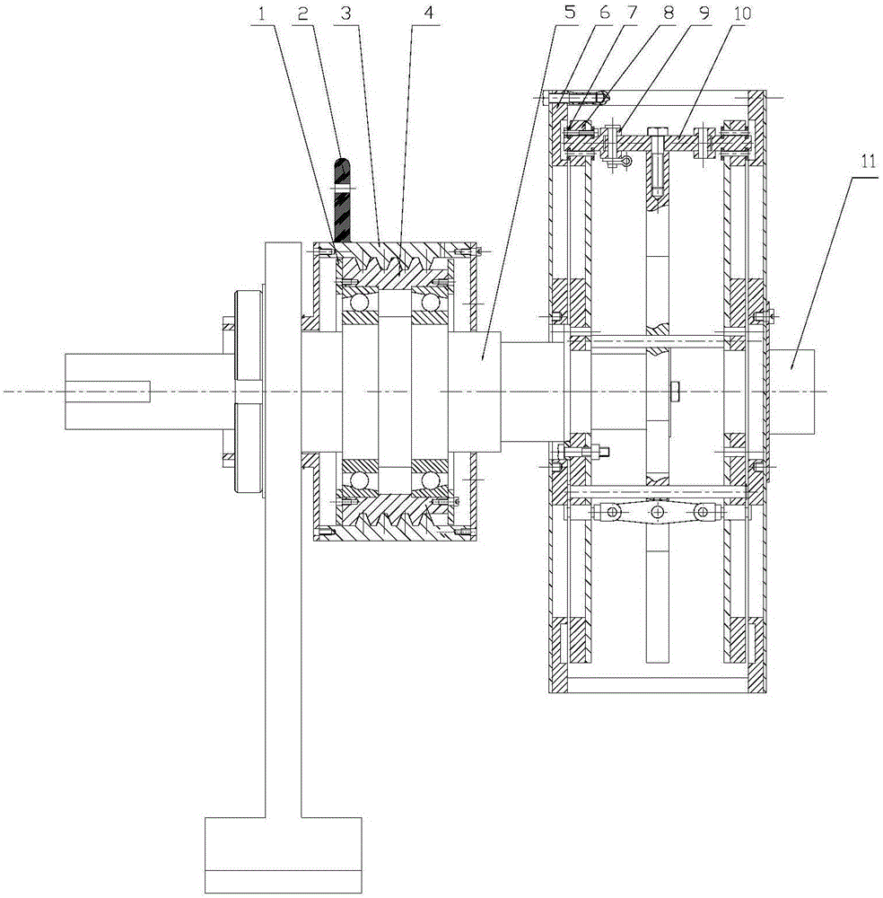
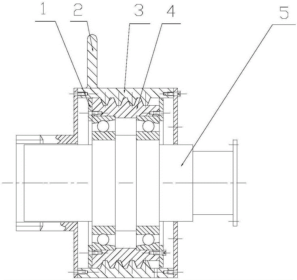
[0025] see figure 1 , the adjustment mechanism of the adjustable shaft coupling provided by the present invention manually rotates the handle 2, and the outer cylinder 3 produces a rotational displacement and transmits it to the inner cylinder 4 through a screw thread, and the inner cylinder side cover 1 fixed on the inner cylinder 4 pushes the bearing outer sleeve As a result, the stepped shaft 5 is driven to move toward the coupling, and the inner rotor 8 connected to the stepped shaft 5 through the bolts is displaced in the same direction, and then the inner rotor 8 is shrunk inward through the fork 9 and the adjusting frame 10, thus changing the The air gap between the outer rotor 7 and the inner rotor 8 changes, and the eddy current effect is generated to drive the output shaft connector 11 connected to the outer rotor 6 by bolts to rotat...


PUM


Abstract

The invention discloses an adjustable permanent magnet coupler and belongs to the technical field of couplers. The adjustable permanent magnet coupler comprises an adjusting mechanism and a coupler mechanism. The adjusting mechanism is detachably arranged on a stepped shaft, the stepped shaft is sleeved with an angular contact ball bearing, the angular contact ball bearing is fixedly connected with an inner barrel, and the inner barrel and an outer barrel are connected in a threaded mode. The stepped shaft is fixedly connected to an inner rotor of the coupler, an outer rotor of the coupler is fixedly connected with a load, and the rotating speed of the coupler is changed along with the change of an air gap between the inner rotor and the outer rotor. Magnetic steel is attached to the interior of the rotors, in addition, and the inner rotor and the outer rotor are provided with baffles used for being attached to the magnetic steel. The inner rotor is of a combined structure, and comprises a triangular plate frame on the inner layer and magnetic steel plates symmetrically located on the two sides, the triangular plate frame and the magnetic steel plates are guided by pin shafts, a branch mechanism is arranged and fixedly connected to the triangular plate frame to penetrate through the magnetic steel plates, and pressing plates are arranged on the two sides of the magnetic steel plates for fastening. The structure is simple, speed regulating is convenient, and the function of manually adjusting the rotating speed in a non-contact mode can be achieved.

Description

[0001] Technical field: [0002] The invention belongs to the technical field of shaft couplings, and in particular relates to a permanent magnetic shaft coupling capable of manually adjusting the speed without contact. [0003] Background technique: [0004] Permanent magnet couplings can be widely used in centrifugal pumps and centrifugal fans in industries such as power generation, metallurgy, petrochemical, mining, papermaking, water supply, water affairs, cement, and irrigation. There is no mechanical connection between the inner rotor and the outer rotor of the coupling, and they can rotate freely and independently. When the inner rotor rotates, the inner rotor and the outer rotor move relative to each other, the alternating magnetic field generates eddy currents, and the eddy currents generate induced magnetic fields. The permanent magnetic fields interact to drive the outer rotor to rotate in the same direction as the inner rotor. However, the generation of the alterna...

Claims


Application Information

Patent Timeline
IPC IPC(8): H02K49/10H02K7/10F16H25/20
CPCH02K7/10H02K49/108F16H25/20
Inventor 刘庆运刘涛景甜甜
Owner ANHUI UNIVERSITY OF TECHNOLOGY
Why Eureka
Try Eureka