Novel annular combustion chamber oil-fired gas-fired boiler
A gas-fired boiler and combustion chamber technology, applied to steam boilers, fluid heaters, steam generation, etc., to achieve the effects of small volume, large variable range, and reduced manufacturing difficulty
- Summary
- Abstract
- Description
- Claims
- Application Information
AI Technical Summary
Problems solved by technology
Method used
Image

Examples
Embodiment 1
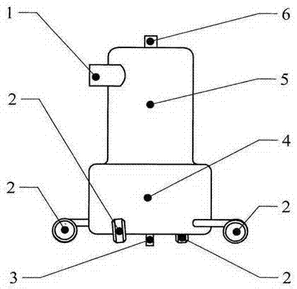
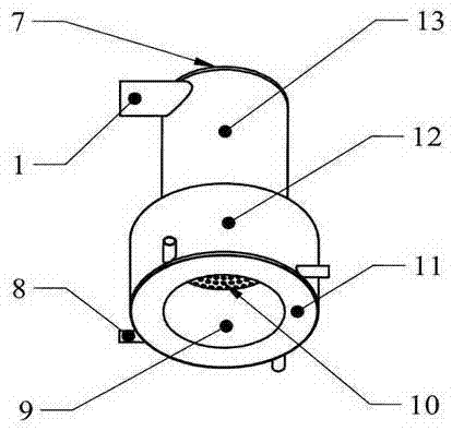
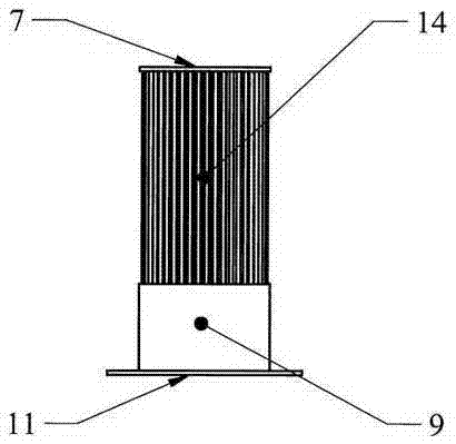
[0017] Embodiment 1: The structure of a novel annular combustion chamber fuel gas steam boiler is as follows figure 1 as shown, figure 2 is the furnace structure diagram, image 3 It is the internal structure diagram of its furnace. The pot shell is arranged upright, four burners 2 are arranged in the same direction along the tangent line of the furnace outside the pot shell, and the furnace is placed in the center of the pot shell. The upper cylinder 5 of the pot shell has an outlet that communicates with the outside of the pot shell and the flue gas discharge pipe 1 in the furnace. There are 4 inlets of pipelines 8 communicating with the outside of the pot shell and the combustion chamber in the furnace gall on the bottom cylinder 4 of the pot shell. The flame injection pipe of the burner 2 is inserted into the combustion chamber through the pipeline 8 connecting the outside of the pot shell and the combustion chamber in the furnace. The pipe 8 connecting the outside of...
Embodiment 2
[0019] Embodiment 2: The structure of the new type annular combustion chamber fuel gas hot water boiler is as follows Figure 4 As shown, only one burner is configured due to the small heating power. The water inlet pipe 16 of the hot water boiler is arranged on the top of the pot shell, the water outlet pipe is arranged on the annular combustion chamber, the water outlet pipe leads into the annular hot water tank 15 outside the upper cylinder of the pot shell, and a hot water valve is installed on the hot water tank 15 .
[0020] The working process of embodiment 2 is: the water inlet pipe 16 of the hot water boiler connects the tap water pipe and connects tap water, and the burner ignites and burns. Water temperature just can open the hot water valve on the hot water tank 15 and get hot water when water temperature reaches prescribed temperature. The tap water pipe automatically replenishes water.
PUM
 Abstract
Description
Claims
Application Information
PatSnap Eureka turns technology decisions into work you can execute. Powered by our Innovation Knowledge Graph, it runs expert workflows across engineering, life sciences, materials and intellectual property. Get your review-ready output in minutes.


