Heat pump drying equipment with dehumidification and humidity elimination switching function and drying method

A switching function and heat pump drying technology, which is applied to lighting and heating equipment, heat pumps, drying solid materials, etc., can solve the problems of low efficiency, low energy efficiency of evaporator dehumidification, and great influence on material characteristics, so as to achieve low energy consumption and reduce Drying cost, compact structure effect

Active Publication Date: 2017-06-16
HENAN BAIHENG ENERGY SAVING TECH
View PDF7 Cites 31 Cited by
  • Summary
  • Abstract
  • Description
  • Claims
  • Application Information

AI Technical Summary

Problems solved by technology

[0006] The above two types of drying equipment have their own characteristics, and their advantages and disadvantages are also obvious.
The hot air dehumidification mode is greatly affected by the state of the cold air outside, and the efficiency is relatively low when the outside world i...

Method used


Image

  • Heat pump drying equipment with dehumidification and humidity elimination switching function and drying method
  • Heat pump drying equipment with dehumidification and humidity elimination switching function and drying method
  • Heat pump drying equipment with dehumidification and humidity elimination switching function and drying method

Examples


Embodiment Construction

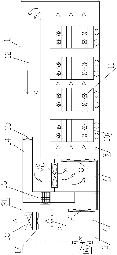
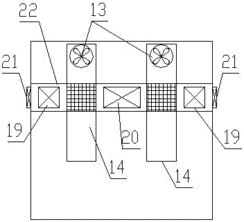
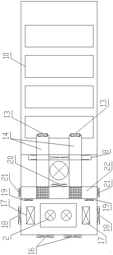
[0047] The direction indicated by the arrow in each view is the airflow direction at that place.

[0048] like Figure 1 to Figure 9 As shown, the heat pump drying equipment with dehumidification type and dehumidification type switching function of the present invention includes a heat pump system and a drying workshop 1, and the drying workshop 1 is provided with a heat pump main engine room 3 and a return air duct 12 from left to right. and a drying chamber 9 for storing materials; the top of the return air duct 12 is higher than the drying chamber 9 and extends to the right, and the right side of the drying chamber 9 is provided with an air outlet, and the air outlet communicates with the return air duct 12 ;

[0049] Heat pump host room 3 bottom side is provided with heat pump host room damper 16, and heat pump host room 3 is connected with exhaust room 31 upward; The other end extends into the exhaust chamber 31 and extends downward into the lower part of the heat pump ...


PUM


Abstract

The invention discloses heat pump drying equipment with a dehumidification and humidity elimination switching function and a material drying method. The heat pump drying equipment comprises a heat pump system and a drying workshop, wherein the drying workshop is internally provided with a heat pump host machine room, a return air passage and a drying room; the top of the return air passage is higher than the drying room, and an air outlet communicated with the return air passage is formed in the right side of the drying room; the return air passage is internally provided with a humidity elimination air passage, and the other end of the humidity elimination air passage stretches into the heat pump host machine room; an internal circulation air door is arranged between an exhausting room and the heat pump host machine room, and an exhaust air door is arranged on the side wall of the exhausting room; the heat pump host machine is internally provided with a fresh air passage, a heat recycling device is arranged at the joint of the fresh air passage and the humidity elimination passage, and an internal fresh air door is arranged on the fresh air passage. The heat pump drying equipment with the dehumidification and humidity elimination switching function disclosed by the invention is compact in structure, and is matched with the drying method; optimal operation modes can be selected according to specific conditions, all advantages of each mode are synthesized, the influences of the defects of each mode are reduced through mode switching, the energy consumption is low, and the drying efficiency is high.

Description

technical field [0001] The invention relates to a heat pump drying device, in particular to a special device and a drying method suitable for dehydration and drying of agricultural by-products and the like. Background technique [0002] At present, heat pump drying equipment has broad development prospects in the field of drying equipment, especially in the field of drying where the drying temperature is below 75°C. As the country pays more and more attention to energy conservation and environmental protection, the application of heat pump drying equipment has attracted more and more attention. [0003] Heat pump drying equipment is a special equipment for material drying. The heat pump system provides heat supply for the drying equipment, and sends the heated airflow into the drying chamber. The high-temperature dry airflow takes away the water vapor in the material, so as to achieve the purpose of drying. When using circulating air, as the high-temperature airflow continu...

Claims


Application Information

Patent Timeline
IPC IPC(8): F26B23/10F25B30/02F26B21/08F26B21/10F26B21/00F26B25/00
CPCF25B30/02F26B21/00F26B21/08F26B21/10F26B23/10F26B25/00Y02P70/10
Inventor 程烨杨德亮都洪阳张二宾孟祥坤卢邦纬来海燕高宇
Owner HENAN BAIHENG ENERGY SAVING TECH
Why Eureka
Try Eureka