CPLD-based brushless motor electronic commutation method

An electronic commutation, brushless motor technology, applied in the field of servo system control, can solve the problems of occupying memory, reducing control reliability, and no motor power-on self-checking function, achieving high reliability, preventing bridge arm pass-through, interface simple effect

Inactive Publication Date: 2017-06-16
SHANGHAI XINYUE METER FACTORY
View PDF5 Cites 3 Cited by
  • Summary
  • Abstract
  • Description
  • Claims
  • Application Information

AI Technical Summary

Problems solved by technology

[0003] The key and difficult point of brushless DC motor control is to ensure correct commutation and judge the rotation direction of the motor in time. The existing method is to solve the above problems through single-chip microcomputer or DSP, but this method will occupy the single-chip microcomputer when designing the motor commutation. Or DSP memory, which conflicts with the motor control system software, reducing the reliability of the control
[0004] Moreover, the existing brushless DC motor control method does not have a motor power-on self-test function, and cannot output a motor self-test signal (BIT signal)

Method used


Image

  • CPLD-based brushless motor electronic commutation method
  • CPLD-based brushless motor electronic commutation method
  • CPLD-based brushless motor electronic commutation method

Examples


Embodiment Construction

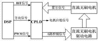
[0014] The present invention will be further described below in conjunction with the accompanying drawings and embodiments. Such as figure 1 As shown, the CPLD obtains the direction signal and PWM signal from the DSP, combines the Hall position signal of the motor, and outputs 6 control signals to the motor drive circuit to drive the motor to rotate.

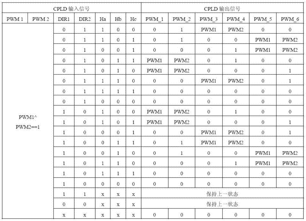
[0015] 1. The input signals of CPLD include: PWM signals PWM1 and PWM2 output by two DSPs; direction signals DIR1 and DIR2 output by two DSPs; three motor Hall position signals Ha, Hb and Hc. The output signals of CPLD include: six-way PWM control signals PWM_1~PWM_6, the logic switching of which is shown in Table 1.

[0016] Table 1 Motor Logic Switching Table

[0017]

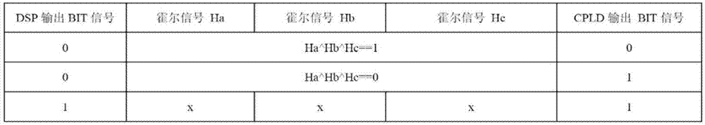
[0018] 2. The CPLD receives the BIT signal output by the DSP and the Hall position signal of the motor, and outputs an effective motor self-test BIT signal in real time. Its logical switching is shown in Table 2.

[0019] Table 2 Motor self-test BIT sign...


PUM


Abstract

The invention discloses a CPLD-based brushless motor electronic commutation method. The method comprises the following steps: with a CPLD being an operation platform, receiving a direction signal output by a DSP and a Hall position signal of a motor; switching a PWM signal output by the DSP to an appropriate PWM control channel in real time to finish electronic commutation work of the motor; and meanwhile, according to a BIT signal output by the DSP and the motor Hall signal, judging and outputting a motor BIT self-checking signal in real time. Compared with the prior art, the method has the advantage and beneficial effects that motor rotation direction is judged in time and correct commutation of the motor is ensured; each path of PWM signal output by the CPLD controls a switch of one MOS transistor, thereby realizing PWM signal single-line injection; interfaces are simple; when the direction signal jumps, automatic insertion to a dead zone is realized, thereby preventing bridge arm direct connection; and reliability is high.

Description

technical field [0001] The invention relates to the technical field of servo system control, in particular, adopts CPLD to realize correct phase commutation of the brushless direct current motor, thereby realizing the control of the brushless direct current motor. Background technique [0002] At present, due to the advantages of reliable operation, high work efficiency, and convenient maintenance, brushless DC motors have been widely used in the field of servo control. [0003] The key and difficult point of brushless DC motor control is to ensure correct commutation and judge the rotation direction of the motor in time. The existing method is to solve the above problems through single-chip microcomputer or DSP, but this method will occupy the single-chip microcomputer when designing the motor commutation. Or DSP memory, conflicts with the motor control system software in it, reducing the reliability of the control. [0004] Moreover, the existing brushless DC motor contro...

Claims


Application Information

Patent Timeline
Patent Type & Authority Applications(China)
IPC IPC(8): H02P6/14
CPCH02P6/14
Inventor 汤伟王蕾张军
Owner SHANGHAI XINYUE METER FACTORY
Why Eureka
Try Eureka