Eureka AIR delivers breakthrough ideas for toughest innovation challenges, trusted by R&D personnel around the world.

Hydraulic drive efficient correction leveling assembly for silicon steel column

A silicon steel and leveling technology, applied in the field of silicon steel column processing devices, can solve the problems of affecting the correction effect, correction failure, and unstable deformation position of the silicon steel column, so as to achieve the effect of improving the accuracy of the effect, reducing the correction error, and adapting the position setting

Inactive Publication Date: 2017-06-20
四川省隆昌诚信印务有限公司
View PDF1 Cites 2 Cited by
  • Summary
  • Abstract
  • Description
  • Claims
  • Application Information

AI Technical Summary

Problems solved by technology

[0003] In the patent titled "Silicon Steel Column Plane Calibration Device" and the patent number "CN201620350955.4", the applicant disclosed a calibration device with high calibration efficiency, labor-saving and convenient calibration, but as an old-fashioned calibration device, the There are the following technical defects: 1. The structure of the device is complex when controlling the clamping device and the transmission device. When adjusting the toggle lever, the driving gear is easily jammed with the transmission gear and the worm, which affects the transmission adjustment; 2. When clamping the silicon steel column When using the first support block and the second support block to clamp, but there is a gap between the two, the flatness of the silicon steel column cannot be guaranteed when the pneumatic hydraulic press is used to correct the pressure, and it is also very easy to It is bent downward, causing the calibration to fail, and it is impossible to realize the calibration of the silicon steel column stably and efficiently; 3. Due to the indeterminate width of the silicon steel column, the deformation position of the silicon steel column is uncertain. It is impossible to adjust the translation, and it is impossible to adjust the deformation. The correction is incomplete and the effect is poor. Although the patent mentions the use of sliders and slide rails to realize the small-scale movement of the pneumatic hydraulic machine, due to the existence of problem 2, Even if the pneumatic hydraulic machine can move, it cannot ensure that the silicon steel column is evenly stressed and will not be deformed again, and its function is poor; In the limit groove, but due to the influence of the width of the limit groove, the silicon steel column is easily warped and deformed during calibration, which affects the calibration effect; The pressure is high, which will lead to deformation of the upper and lower ends of the base during long-term use, resulting in the inability to achieve a complete fit between the pressing plane and the surface of the silicon steel column during calibration, and a gap between the two is very likely to occur or even the gap is too large to cause calibration Ineffective, not conducive to long-term stable calibration and use

Method used


Image

  • Hydraulic drive efficient correction leveling assembly for silicon steel column
  • Hydraulic drive efficient correction leveling assembly for silicon steel column
  • Hydraulic drive efficient correction leveling assembly for silicon steel column

Examples


Embodiment 1

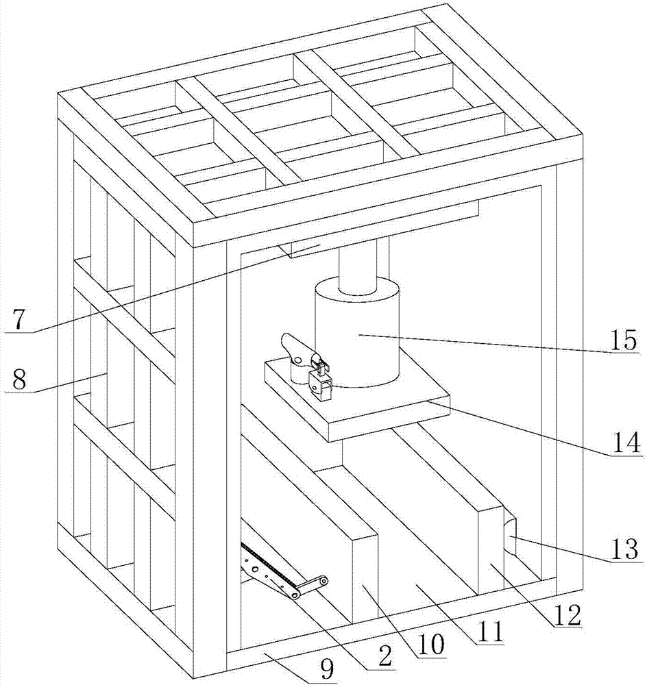
[0034] A silicon steel column hydraulic high-efficiency correction and leveling assembly, which includes a square frame 9 composed of four metal plates, the front and rear sides of the square frame 9 are open. A vertical correction device and a horizontal correction device are arranged in the square frame body 9. The vertical correction device can correct and level the silicon steel column from the vertical direction, and the horizontal correction device can correct and level the silicon steel column from the horizontal direction. And when in use, the horizontal correction device and the vertical correction device cooperate to correct and level the silicon steel column from both horizontal and vertical directions. The first clamping plate 12 and the second clamping plate 10 oppositely arranged on the inner bottom surface of the square frame body 9, the second clamping plate 10 can slide horizontally relative to the first clamping plate 12, and an adjustable spacing is formed be...

Embodiment 2

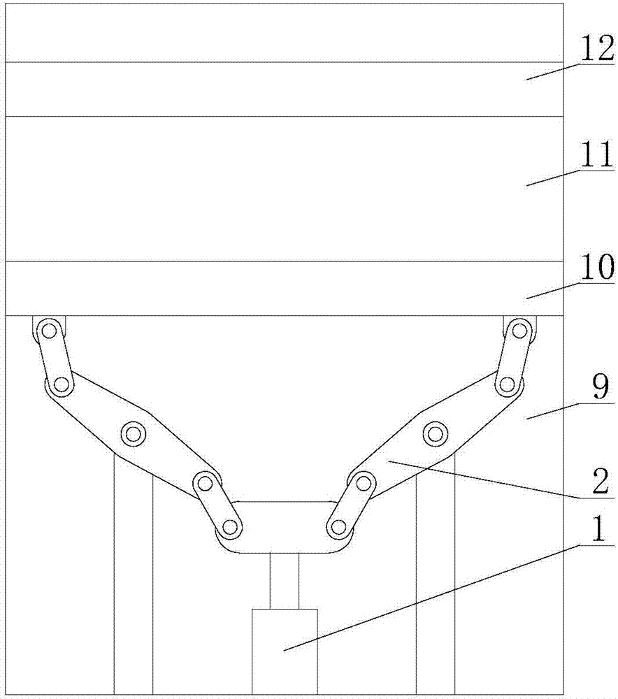
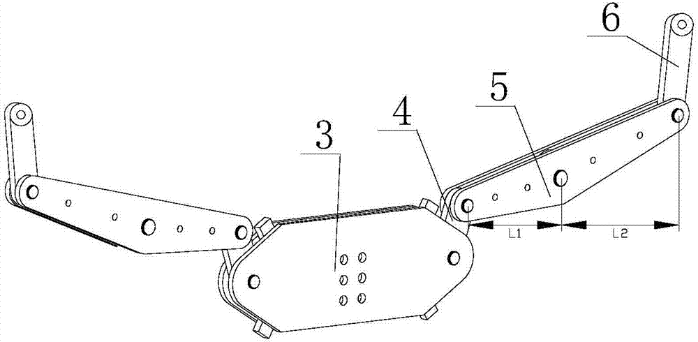
[0036] On the basis of the first embodiment, the pushing mechanism 2 includes a translation block 3 which is directly connected to the drive shaft of the hydraulic cylinder 1 and slides under the action of the hydraulic cylinder 1 . Both ends of the translation block 3 are hinged with first cranks 4 , and the ends of the other ends of each set of first cranks 4 are hinged with rotating rods 5 . The middle part of the rotating rod 5 is hinged with the square frame body 9 so that the rotating rod 5 can rotate in the square frame body 9 . The other end of the rotating rod 5 is hinged with a second crank 6 , and the other end of the second crank 6 is hinged with the first splint 12 or the second splint 10 . Two sets of first cranks 4 , rotating rods 5 and second cranks 6 are symmetrically arranged on the left and right sides of the translation block 3 . When the hydraulic cylinder 1 operates, it will drive the translation block 3 to move, and the movement of the translation block...

Embodiment 3

[0038] Based on the second embodiment, on the rotating rod 5 , the length of the first moment arm L1 of the rotating rod 5 is smaller than the length of the second moment arm L2 of the rotating rod 5 . The length of the first moment arm L1 refers to the distance between the two hinge points between the hinge point where the swing rod 5 and the first crank 4 are hinged and the hinge point where the swing rod 5 and the square frame 9 are hinged on the swing rod 5; The length of the second moment arm L2 refers to the distance between the hinge point on the rotating rod 5 where the rotating rod 5 and the second crank 6 are hinged and the hinge point where the rotating rod 5 and the square frame 9 are hinged.


PUM


Abstract

The invention relates to a silicon steel column hydraulic high-efficiency correction leveling assembly, which belongs to the technical field of silicon steel column processing, and aims to provide a silicon steel column hydraulic high-efficiency correction leveling assembly with good correction effect and high correction efficiency. It includes a square frame body, the inner bottom surface of the square frame body is provided with a first splint and a second splint, and a silicon steel column correction and leveling channel with adjustable spacing is formed between the first splint and the second splint; The inner bottom surface of the square frame is provided with a horizontal correction device for horizontal correction and leveling of the silicon steel column, and the inner top surface of the square frame is provided with a vertical correction device for vertical correction and leveling of the silicon steel column The level correction device includes a hydraulic cylinder, the end of the drive shaft of the hydraulic cylinder is connected with a push mechanism, and the push mechanism is connected with the first splint or the second splint so that the second splint can slide horizontally relative to the first splint. The invention is suitable for correction and leveling of silicon steel columns.

Description

technical field [0001] The invention belongs to the technical field of silicon steel column processing, and relates to a silicon steel column processing device. Background technique [0002] After the silicon steel column is welded to the water tank for auxiliary heat dissipation, due to the high temperature of welding, the silicon steel column is easily deformed, and the side of the water tank will be uneven, which will affect the normal use of the silicon steel column. Perform calibration and leveling. [0003] In the patent titled "Silicon Steel Column Plane Calibration Device" and the patent number "CN201620350955.4", the applicant disclosed a calibration device with high calibration efficiency, labor-saving and convenient calibration, but as an old-fashioned calibration device, the There are the following technical defects: 1. The structure of the device is complex when controlling the clamping device and the transmission device. When adjusting the toggle lever, the dr...

Claims


Application Information

Patent Timeline
Patent Type & Authority Applications(China)
IPC IPC(8): B21D3/10
CPCB21D3/10
Inventor 黄绍旭梁春
Owner 四川省隆昌诚信印务有限公司
Why Eureka
Eureka Blog
Learn More