
A method for processing workpieces

A processing method and workpiece technology, applied in the field of workpiece processing, can solve problems such as defective appearance of parts, insufficient number of CNC lathes, delay in construction period, etc., so as to solve general processing problems, improve processing quality and processing efficiency, and reduce clamping positions. Effect

Active Publication Date: 2018-09-14
GEER TECH CO LTD
View PDF5 Cites 0 Cited by
  • Summary
  • Abstract
  • Description
  • Claims
  • Application Information

AI Technical Summary

Problems solved by technology

[0005] In the daily processing and production process, the construction period is often delayed due to tight construction schedules, heavy tasks, and insufficient number of CNC lathes. At this time, the use of CNC machining centers to process shaft parts according to the existing processing methods is relatively slow. , the appearance brightness of the processed parts will be flawed, and the efficiency is obviously lower than that of CNC lathes. Although it is possible to use CNC machining centers instead of CNC lathes to process round shaft workpieces by using processing devices, the existing processing paths used by traditional CNC machining centers , can only realize machining in the positive Z direction on the surface of the workpiece and the outer wall, but the circular shaft products sometimes need to process the inner cavity structure in the negative Z direction, and the processing paths used by the existing traditional CNC machining centers cannot meet the processing requirements

Method used


Image

  • A method for processing workpieces
  • A method for processing workpieces
  • A method for processing workpieces

Examples


Embodiment Construction

[0039] In order to make the object, technical solution and advantages of the present invention clearer, the present invention will be further described in detail below in conjunction with the accompanying drawings and embodiments. It should be understood that the specific embodiments described here are only used to explain the present invention, not to limit the present invention.

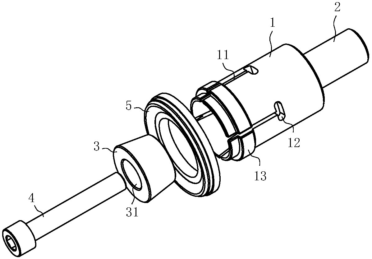
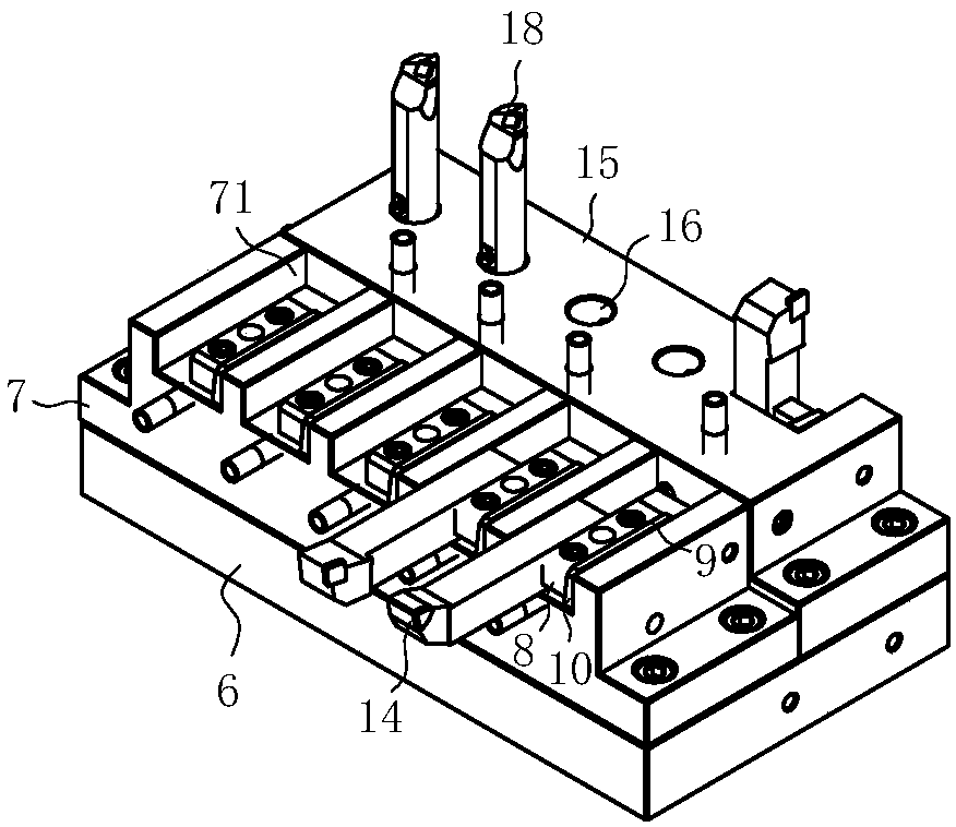
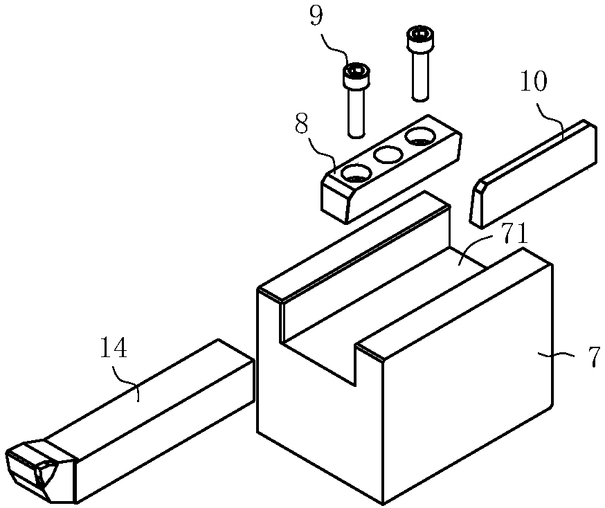
[0040] like figure 1 and figure 2 As shown, the workpiece fixing device includes a support tube 1 and a tool seat fixedly arranged on the workbench of the CNC machining center. The tool seat includes a base 6, and a horizontal tool seat 7 and a vertical tool seat 15 are fixedly installed on the base 6. The horizontal tool seat 7 is equipped with the cutting tool 14 of cutting workpiece 5, and the cutting tool 18 of cutting workpiece 5 is installed on the vertical knife seat 15.

[0041] like figure 1 As shown, one end of the support tube 1 is open and a workpiece limiting boss 13 is provided on...


PUM


Abstract

The invention discloses a workpiece machining method and relates to the technical field of mechanical machining. According to the workpiece machining method, a workpiece fixing device installed on a main shaft of a numerical control machining center and a tool apron for installing cutters and fixed to a workbench of the numerical control machining center are included, and a machining path is furthermore included. The machining path generating process includes the steps that (1), a precise three-dimensional graph with the proportion being 1: 1 is drawn through software according to the structure of a workpiece to be machined; (2), the machining region of the three-dimensional graph is determined, and then the three-dimensional graph is cut according to an X-Z plane; (3), a cutting plane line and a center line of the three-dimensional graph are extracted, the extracted cutting plane line is subjected to deviation according to the size of the machining region; (4), the deviated cutting plane line is rotated by 180 degrees with the X axis as the main axis and the center point as the benchmark, and finally the rotated cutting plane line is selected as the machining program to generate the machining path. By means of the workpiece machining method, the numerical control machining center for the workpiece can replace numerical control lathe machining, the requirement for machining a Z-negative direction structure of the workpiece is met, and work efficiency is improved.

Description

technical field [0001] The invention relates to the technical field of mechanical processing, in particular to a processing method for workpieces. Background technique [0002] Numerical control lathe (NCC) is a high-precision, high-efficiency automatic machine tool. Equipped with a multi-station turret or a power turret, the machine tool has a wide range of processing performance, and can process complex workpieces such as straight cylinders, oblique cylinders, arcs, and various threads, grooves, worms, etc., with linear interpolation, arc Various compensation functions are interpolated, and play a good role in the mass production of complex parts. The processing principle is: the tool is fixed on the cutter head, and the spindle drives the workpiece to rotate for active cutting. [0003] CNC machining center (CNC) is a high-efficiency automatic machine tool suitable for processing complex parts composed of mechanical equipment and numerical control system. Its comprehens...

Claims


Application Information

Patent Timeline
Patent Type & Authority Patents(China)
IPC IPC(8): B23B1/00B23B5/08B23B29/04
CPCB23B1/00B23B5/08B23B29/04
Inventor 王国龙石丁宇田兆健
Owner GEER TECH CO LTD
Learn More