A backfilling friction stir spot welding method

A friction stir and spot welding technology, used in welding equipment, non-electric welding equipment, metal processing equipment, etc., can solve the problems of insufficient mixing of connecting ligament and base material, low flow speed of material in the center of the welding spot, and short material contact time. , to achieve the effect of reducing interface defects, improving joint performance and improving joint quality

Active Publication Date: 2019-02-19
SHENYANG AEROSPACE UNIVERSITY
View PDF7 Cites 1 Cited by
  • Summary
  • Abstract
  • Description
  • Claims
  • Application Information

AI Technical Summary

Problems solved by technology

[0004] 1. Limited by the special structure and movement mode of the RFSSW stirring head, the flow velocity of the material in the center of the solder joint is often low, resulting in coarser grains, insufficient mixing of the connecting ligament and the base material, etc.
[0005] 2. The faster retraction speed of the sleeve during the welding process can lead to a shorter contact time between the nugget area and the heat engine affected area in the near surface area of ​​the joint, and the weaker degree of atomic diffusion, which can easily lead to tearing defects after welding
[0006] 3. Since the outer wall of the stirring pin and the outer wall of the sleeve of the RFSSW stirring head are provided with threaded grooves and the components of the stirring head adopt clearance fit, a part of the plastic material will be "trapped" in the gap of the stirring head during the welding process. Difficult to backfill into the joint after welding, resulting in depressions in the welded surface

Method used


Image

  • A backfilling friction stir spot welding method
  • A backfilling friction stir spot welding method
  • A backfilling friction stir spot welding method

Examples


Embodiment Construction

[0030] The present invention will be further described below in conjunction with the accompanying drawings and embodiments.

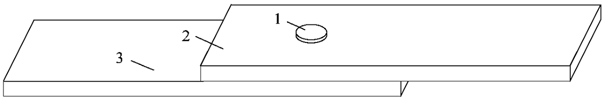
[0031] This embodiment adopts the method of the present invention to weld figure 1 The workpiece shown is a 2024-T4 aluminum alloy plate, the thickness of the upper plate 2 and the lower plate 3 are respectively 2mm, and the welding part of the upper plate has a circular bump 1 reserved during processing, and the circular bump The diameter is 9mm and the height is 0.2mm.

[0032] The welding operation steps are as follows:

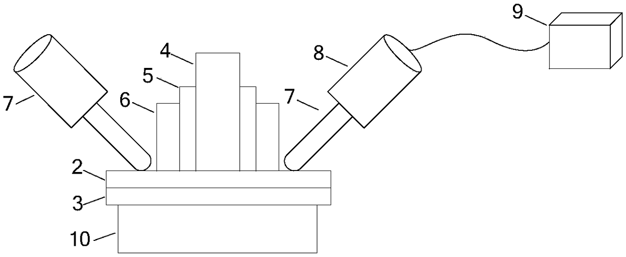
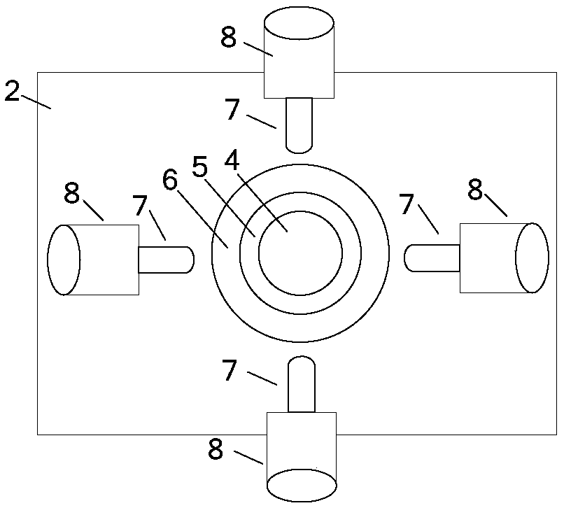
[0033] Step 1, select the stirring head, such as figure 2 with image 3 As shown, the diameter of the stirring needle 4 is 5 mm, and the outer wall has a right-handed thread (not shown); the inner and outer diameters of the sleeve 5 of the stirring needle are 5.2 mm and 9 mm, and the outer wall of the sleeve has a right-handed thread (not shown), the inner diameter and outer diameter of the compression ring 6 outside the sleeve...


PUM

PropertyMeasurementUnit
thicknessaaaaaaaaaa
diameteraaaaaaaaaa
heightaaaaaaaaaa

Abstract

The invention discloses a refill friction stir spot welding method which is characterized in that a circular convex block is arranged at a welding spot of an upper plate of a workpiece; during welding, a hold-down ring of a stirring head is contacted with the upper plate and surrounds the convex block, and a stirring needle and a sleeve are contacted with the convex block; with the application of ultrasonic vibration to positions, on the outer side of the hold-down ring, of the upper plate, a material in a welding zone is plastified through the rotation of the sleeve and the stirring needle, then the sleeve pricks downwards to penetrate through the upper plate and pricks into a lower plate by a certain depth, the stirring needle is drawn back with the downward pricking of the stirring needle, after the sleeve reaches the designed downward pricking depth, the sleeve and the stirring needle return to initial positions, and continue to rotate and press down in the initial positions to allow the surface of the welding spot to be smooth, and after the stirring head stops rotating, an operator continues to apply the ultrasonic vibration for a certain time. According to the refill friction stir spot welding method, by employing the convex block for compensation, a pit of the welding spot produced after the welding can be eliminated; through the ultrasonic vibration, material flowing and material exchange between the upper plate and the lower plate can be improved, and the joint quality is improved; and the operator continues to apply the ultrasonic vibration after the welding, so that the residual stress of the welding spot can be reduced.

Description

technical field [0001] The invention relates to friction stir welding, in particular to a backfilling friction stir spot welding method. Background technique [0002] Refill friction stir spot welding (Refill friction stir spot welding, RFSSW) is a new spot welding technology proposed by the German GKSS Center in 2002. RFSSW has attracted extensive attention from scholars at home and abroad because it has no keyhole after welding. In recent years, it has gradually developed into a new technology that can replace traditional spot welding methods such as riveting and resistance spot welding. It is widely used in aerospace, automotive, Welding of commonly used light metals such as aluminum alloy and magnesium alloy in shipbuilding and other fields. [0003] At present, there are still the following unresolved technical problems in RFSSW: [0004] 1. Limited by the special structure and movement mode of the RFSSW stirring head, the flow rate of the material in the center of th...

Claims


Application Information

Patent Timeline
Patent Type & Authority Patents(China)
IPC IPC(8): B23K20/12B23K20/24
CPCB23K20/12B23K20/24
Inventor 姬书得李政玮岳玉梅马琳张利国吕赞
Owner SHENYANG AEROSPACE UNIVERSITY
Why Eureka
Try Eureka