Linear axis geometric error detecting method of five-axis numerically-controlled machine tool

A geometric error, CNC machine tool technology, used in measuring/indicating equipment, metal processing mechanical parts, metal processing equipment, etc., can solve the problem of inability to achieve simultaneous detection of multiple errors, limited measurement accuracy Long cycle and other issues

Active Publication Date: 2017-06-20
DALIAN UNIV OF TECH
View PDF2 Cites 29 Cited by
  • Summary
  • Abstract
  • Description
  • Claims
  • Application Information

AI Technical Summary

Problems solved by technology

The patent number invented by Liu Kuo of Shenyang Machine Tool Co., Ltd. is CN 104097114 A "A Geometric Error Measurement and Separation Technology of Multi-axis Linkage CNC Machine Tool" invented a method for measuring 15 errors of three-axis machine tools with laser interferometer, but Using a laser interferometer has a long measurement period, and the error can only be detected by a single item, and the simultaneous detection of multiple errors cannot be realized; the patent number invented by Guo Junjie of Xi'an Jiaotong University is CN 103737426 A "a three-line measurement method for the geometric error of the rotational axis of a CNC machine tool" using laser The tracker and the supporting cat's eye realize the measurement of the geometric error of the rotation axis of the machine tool. The measurement accuracy is limited by the positioning accuracy of the laser tracker's rotation angle, and the cost of the measurement equipment is relatively high.

Method used


Image

  • Linear axis geometric error detecting method of five-axis numerically-controlled machine tool
  • Linear axis geometric error detecting method of five-axis numerically-controlled machine tool
  • Linear axis geometric error detecting method of five-axis numerically-controlled machine tool

Examples


Embodiment Construction

[0050] The specific embodiments of the present invention will be described in detail below in conjunction with the technical solutions and accompanying drawings.

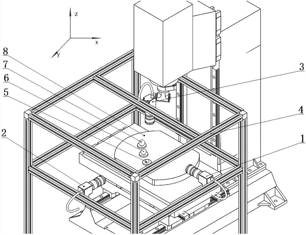
[0051] The invention adopts three cameras to collect image information of a characteristic target ball fixed on a workbench and moves linearly with the machine tool, and through comprehensive data processing, the geometric error of the linear axis of the machine tool is solved. figure 1 It is a diagram of a geometric error detection device for machine tool linear axes based on trinocular vision. Cameras 1, 2, and 3 are installed on the camera adjustment frame 4 respectively, and the characteristic target balls 5 of B, A, and C , 6, 7 are installed on the machine tool table 8 respectively.

[0052] Adjust the position of each camera so that the optical axis of No. 1 camera 1 is parallel to the X-axis direction of the machine tool; the 2 optical axis of No. 2 camera is parallel to the Y-axis direction of the machine t...


PUM


Abstract

The invention discloses a linear axis geometric error detecting method of a five-axis numerically-controlled machine tool, belongs to the technical field of machine tool precision detecting and relates to linear axis geometric error detecting and identifying method of the five-axis numerically-controlled machine tool. The detecting method comprises the following steps that a three-eye measuring unit is set up through three high-resolution cameras, and three self-luminous characteristic target sphere images fixed to a working table and making rectilinear motion along with the X axis or the Y axis of the machine tool are collected; and through combination of camera calibrating, characteristic point position information extracting and measured information of the three cameras, a three-dimensional coordinate of the sphere center of a characteristic target sphere is obtained, and the X and Y axis linear axis geometric errors of the machine tool are measured. According to the linear axis geometric error detecting method, linear axis error measuring efficiency of the numerically-controlled machine tool is effectively improved, a complex identifying model and a fussy measuring process are avoided, and linear axis geometric error measuring of the numerically-controlled machine tool is achieved; and the linear axis geometric error detecting method has the characteristics of being convenient, rapid, high in noise-resisting property, good in robustness and capable of simultaneously measuring the geometric errors of the multiple linear axes of the machine tool.

Description

technical field [0001] The invention belongs to the technical field of machine tool precision detection, and relates to a linear axis error detection and identification method of a five-axis numerical control machine tool. Background technique [0002] With the development of aviation, aerospace, and ship technology, parts with complex spatial and cross-scale structures have gradually become core components in various fields. In addition, these parts, such as engine impellers and marine propellers, often use complex processes to ensure sufficient strength and rigidity. The efficient and high-quality processing of parts directly affects the working performance of the equipment, and has high requirements on the performance of machine tools. Five-axis CNC machine tools are widely used in the manufacture of complex and difficult-to-machine parts due to their high flexibility and high-precision machining advantages. However, machine tool design and manufacturing accuracy limit t...

Claims


Application Information

Patent Timeline
Patent Type & Authority Applications(China)
IPC IPC(8): B23Q17/24B23Q17/22
CPCB23Q17/2428
Inventor 刘巍李辉李肖严洪悦贾振元马建伟
Owner DALIAN UNIV OF TECH
Why Eureka
Try Eureka