
Communication base station charging pile integration device

A technology for integrating devices and communication base stations, applied in charging stations, wireless communication, electric vehicle charging technology, etc., can solve the problems of small diameter of single pipe tower, poor user experience, low integration of communication base stations and charging piles, etc. Achieve high integration and improve user experience

Inactive Publication Date: 2017-06-20
江西长林鑫源通信科技有限公司
View PDF6 Cites 6 Cited by
  • Summary
  • Abstract
  • Description
  • Claims
  • Application Information

AI Technical Summary

Problems solved by technology

[0005] In the prior art, there is no integrated single-tube tower charging pile product, and because the charging pile is divided into two types: AC charging pile and DC charging pile, the volume of the charging pile varies greatly, and the diameter of the single-tube tower is determined according to the wind pressure. The larger the wind pressure, the larger the pipe diameter; on the contrary, the smaller the wind pressure, the smaller the pipe diameter. For example, the wind pressure in Jiangxi and other provinces and cities is not large. Therefore, the pipe diameter of the single-pipe tower is relatively small. Small, unable to arrange charging piles. In addition, the integration of existing communication base stations and charging piles is relatively low, resulting in poor user experience

Method used


Image

  • Communication base station charging pile integration device
  • Communication base station charging pile integration device
  • Communication base station charging pile integration device

Examples


Embodiment Construction

[0024] In order to facilitate the understanding of the present invention, the present invention will be described more fully below with reference to the associated drawings. Several embodiments of the invention are shown in the drawings. However, the present invention can be embodied in many different forms and is not limited to the embodiments described herein. Rather, these embodiments are provided so that the disclosure of the present invention will be thorough and complete.

[0025] It should be noted that when an element is referred to as being “fixed on” another element, it may be directly on the other element or there may be an intervening element. When an element is referred to as being "connected to" another element, it can be directly connected to the other element or intervening elements may also be present. As used herein, the terms "vertical," "horizontal," "left," "right," "upper," "lower," and similar expressions are for descriptive purposes only and do not in...


PUM


Abstract

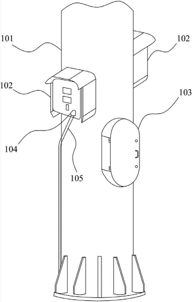
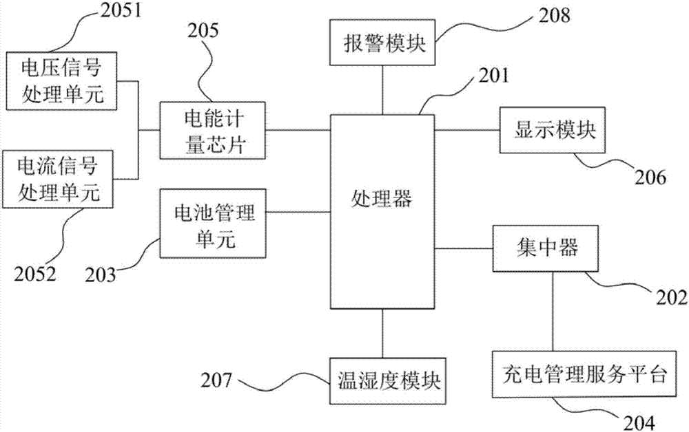
The invention discloses a communication base station charging pile integration device which comprises a communication tower body. A communication single-pipe tower is adopted as the communication tower body. A plurality of wall-mounted charging piles are mounted on the communication tower body. Each wall-mounted charging pile comprises a charging pile shell and a charging pile system arranged inside the charging pile shell. Each charging pile system comprises a processor, a concentrator, a battery management unit, a charging management service platform and an electric energy measuring chip, wherein the processor is in data communication with the concentrator through a CAN bus; the concentrator is in data communication with the charging management service platform through a wired internet or a wireless GPRS network; and the battery management unit is in data communication with the processor through a CAN bus. By adoption of the communication base station charging pile integration device, arrangement of the charging piles of the single-pipe tower with a small tower diameter is achieved, the integration degree of the charging pile systems is high, and the user experience degree can be effectively increased.

Description

technical field [0001] The invention relates to the technical field of electric vehicle charging, in particular to a communication base station charging pile integration device. Background technique [0002] With the rapid development of the automobile industry, my country's dependence on foreign oil consumption continues to increase, and the shortage of oil is becoming increasingly serious. As a green transportation tool with broad development prospects, electric vehicles will be popularized very rapidly in the future, and the future market prospects will be extremely huge. In the context of the global energy crisis and serious environmental crisis, the Chinese government is actively promoting the application and development of new energy vehicles. As an important supporting infrastructure for the development of electric vehicles, charging / swapping stations have very important social and economic benefits. . A movement to build electric vehicle charging / swapping stations ...

Claims


Application Information

Patent Timeline
IPC IPC(8): B60L11/18E04H12/00H04W88/08
CPCB60L53/31E04H12/00H04W88/08Y02T10/70Y02T10/7072Y02T90/12Y02T90/16
Inventor 钟鸣尹文军
Owner 江西长林鑫源通信科技有限公司
Learn More