Variable valve control device and method and engine comprising variable valve control device

A control device and engine technology, applied in the direction of engine components, combustion engines, machines/engines, etc., can solve problems such as limitations in adapting to working conditions, large pump air loss, and increased energy consumption, so as to improve control accuracy and avoid channeling The effect of oil wind and guaranteed phase angle

Active Publication Date: 2017-06-20
WEICHAI POWER CO LTD
View PDF6 Cites 8 Cited by
  • Summary
  • Abstract
  • Description
  • Claims
  • Application Information

AI Technical Summary

Problems solved by technology

However, the valve can only be changed in two or three stages according to the cam position, and it cannot realize continuous valve change, and the adaptation to working conditions has limitations.
Moreover, the existing variable valve technology also has the following disadvantages: the post-treatment thermal man

Method used


Image

  • Variable valve control device and method and engine comprising variable valve control device
  • Variable valve control device and method and engine comprising variable valve control device
  • Variable valve control device and method and engine comprising variable valve control device

Examples


Embodiment Construction

[0032] Exemplary embodiments of the present disclosure will be described in more detail below with reference to the accompanying drawings. Although exemplary embodiments of the present disclosure are shown in the drawings, it should be understood that the present disclosure may be embodied in various forms and should not be limited by the embodiments set forth herein. Rather, these embodiments are provided for more thorough understanding of the present disclosure and to fully convey the scope of the present disclosure to those skilled in the art.

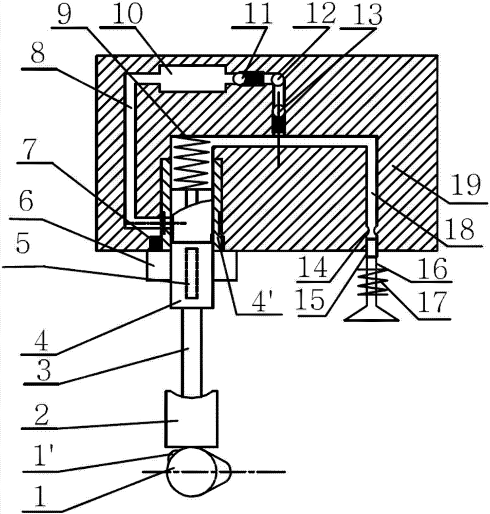
[0033] According to an embodiment of the present invention, a variable valve control device for an engine is proposed, referring to Figure 1-2 , including a gas distribution cam 1, on which a small cam 1' is also processed, the upper part is connected with a tappet 2, a guide rod 3 and a plunger 4 in sequence, the plunger 4 is connected with the plunger fixing device 6 through a key 5, and the cylinder head There is a hydraulic ch...


PUM


Abstract

The invention provides a variable valve control device. In a traditional electro-hydraulic variable valve mechanism, a plunger type oil leakage control mechanism is arranged between a valve train cam and a hydraulic cavity, oil leakage time is controlled by adjusting the relative position between a spiral groove and an oil leakage hole in the plunger type oil leakage control mechanism, and the valve stroke and timing variability are achieved. The invention further provides a variable valve control method. The method can judge function requirements according to whole vehicle and engine operation states and comprises the steps of heat management, miller cycle, exhaust braking and cylinder deactivation and oil cut, and the function requirements are met according to the variable valve control device. The device and the method can be applied to a side-arranged cam shaft engine, and the structure is simple.

Description

technical field [0001] The invention relates to the field of engines, in particular to the field of lateral camshaft engines. Background technique [0002] With the improvement of fuel economy requirements and emission requirements, the demand for new technologies for diesel engines is becoming more and more intense. The traditional engine uses a fixed valve train, and the valve timing takes into account the various working conditions of the engine. It adopts a compromise solution, and cannot achieve the optimal valve timing under all working conditions. Valve timing directly affects the intake performance of the internal combustion engine, and plays a vital role in the quality of the combustion process. Reasonable gas distribution timing can control the concentration and temperature range of the mixed gas in the cylinder, avoid the generation area of ​​NOx and soot, and achieve ultra-low emission. Compared with fixed valve timing, variable valve technology can change the ...

Claims


Application Information

Patent Timeline
IPC IPC(8): F01L13/00F01L9/02F01L9/10F01L9/40
CPCF01L13/0015F01L9/12Y02T10/12
Inventor 李云华陈火雷张朝阳张玲
Owner WEICHAI POWER CO LTD
Why Eureka
Try Eureka