Vehicle active suspension hydraulic servo control system

A control system and active suspension technology, which is applied to servo motors, servo motor assemblies, fluid pressure actuating devices, etc., can solve problems such as whether the actual components can meet the required control force requirements, etc. Stable work and easy maintenance

Inactive Publication Date: 2017-06-20
田佳聪
View PDF0 Cites 6 Cited by
  • Summary
  • Abstract
  • Description
  • Claims
  • Application Information

AI Technical Summary

Problems solved by technology

[0003] In some domestic literature on electro-hydraulic active suspension, the hydraulic actuator is abstracted as an active cont

Method used


Image

  • Vehicle active suspension hydraulic servo control system
  • Vehicle active suspension hydraulic servo control system

Examples


Embodiment Construction

[0016] The present invention will be further described below with reference to the accompanying drawings and embodiments.

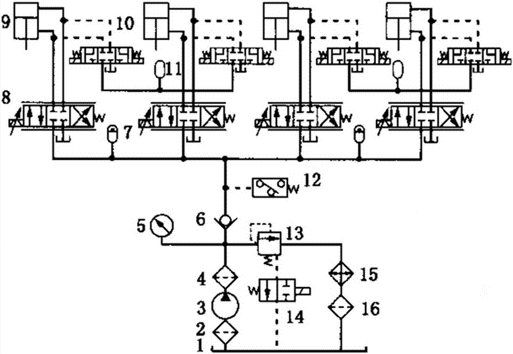
[0017] like figure 1 , The four hydraulic cylinders of the vehicle-based active suspension hydraulic servo control system are respectively connected with the passive components of the vehicle's left front suspension, right front suspension, left rear suspension, and right rear suspension. The action of each hydraulic cylinder of the control system is controlled by a servo valve. Considering the specific situation of the active suspension of the vehicle, a three-position three-way electro-hydraulic reversing valve 10 is connected in parallel with the oil inlet and outlet of the hydraulic cylinder as a bypass. When the servo system cannot work normally, energize the left electromagnet of the bypass valve, and the oil in the upper and lower cavities of the hydraulic cylinder will pass through the bypass valve. At this time, the suspension system is equivalen...


PUM


Abstract

The invention relates to a vehicle active suspension hydraulic servo control system, the four hydraulic cylinders of which are respectively connected with the passive elements of the left front suspension, right front suspension, left rear suspension and right rear suspension. The control system is simple in structure, easy to maintain, adapts to the high-speed and oscillating environment during the driving process of the vehicle, and works stably and reliably.

Description

technical field [0001] The invention relates to a vehicle active suspension hydraulic servo control system, which is suitable for the mechanical field. Background technique [0002] Suspension system is one of the important devices of the car, which affects the ride comfort and stability of the vehicle. From the perspective of control, vehicle suspension can be divided into passive suspension, semi-active suspension and active suspension. Active suspension uses active controllable components to form a closed-loop control system, which can actively respond to road excitation conditions and vehicle motion to improve vehicle performance. At present, most of the vehicle active suspension systems use electro-hydraulic control, which can be roughly divided into high-response flow servo valves and proportional pressure valves. [0003] In some domestic literatures about electro-hydraulic active suspension, the hydraulic actuator is abstracted as an active control force, without c...

Claims


Application Information

Patent Timeline
IPC IPC(8): F15B11/08F15B13/02
Inventor 田佳聪
Owner 田佳聪
Why Eureka
Try Eureka