
Fluid switching electromagnetic valve and endoscope with same

A solenoid valve and endoscope technology, applied in the field of medical devices, can solve the problems of reducing the volume of the operating part, the electrical influence of the circuit board, increasing the weight of the operating part, etc. Effect

Active Publication Date: 2017-06-20
重庆金山医疗技术研究院有限公司
View PDF8 Cites 0 Cited by
  • Summary
  • Abstract
  • Description
  • Claims
  • Application Information

AI Technical Summary

Problems solved by technology

[0007] such as As shown in Figure 7, the above three types of air / water supply fluid switching valves P are all placed in the operating part, occupying the position in the inner cavity of the operating part, hindering the reduction of the volume of the operating part, and at the same time, the fluid switching valve also increases The weight of the operating part
In addition, the air / water fluid switching valve is placed in the inner cavity of the operating part. If the liquid inlet or outlet of the switching valve is not firmly connected with the water and gas pipe, the liquid will leak into the operating part, causing damage to the circuit board or other electrical parts in the operating part. influences

Method used


Image

  • Fluid switching electromagnetic valve and endoscope with same
  • Fluid switching electromagnetic valve and endoscope with same
  • Fluid switching electromagnetic valve and endoscope with same

Examples


Embodiment Construction

[0031] Below in conjunction with accompanying drawing and embodiment the present invention will be further described:

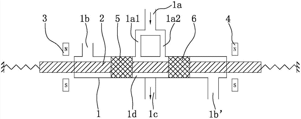
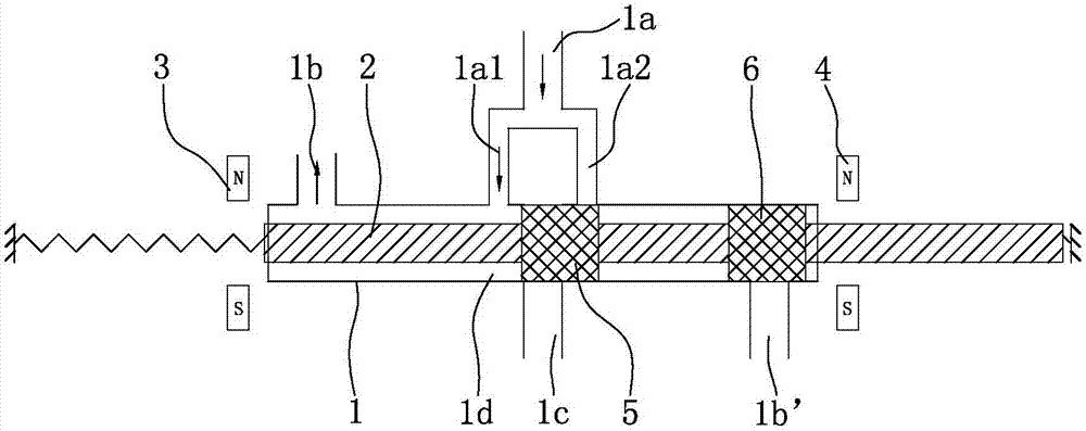
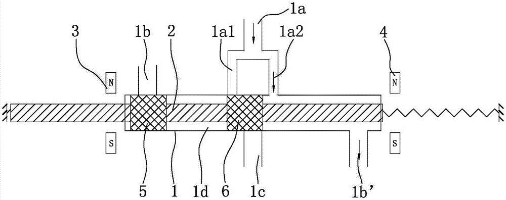
[0032] Such as figure 1 , figure 2 , image 3 As shown, the electromagnetic valve in the present invention is composed of a valve body 1, a valve core 2, a first coil 3, a second coil 4, a first sealing ring 5 and a second sealing ring 6, and the like. Among them, the main air channel 1d of the valve body 1 is a straight pipe structure, and an air inlet 1a and an air port 1c are arranged in the middle of the valve body 1, the air inlet 1a is located on one side of the valve body 1, and the air port 1c is located on the valve body 1 The other side, and the air port 1c is facing the air inlet 1a. Of course, as an equivalent alternative, the air inlet 1a and the air port 1c can also be arranged on the same side of the valve body 1, or the position of each air port on the valve body 1 can be set according to actual needs. The outlet end of the air inlet 1a ...


PUM


Abstract

The invention discloses a fluid switching electromagnetic valve. According to the fluid switching electromagnetic valve, an air inlet and an air port are formed in the middle of a valve body; a first air outlet and a second air outlet are formed in the left end and the right end of the valve body respectively; a valve core passes through a main air channel of the valve body; a first sealing ring and a second sealing ring are arranged on the valve core; and the two sealing rings control the air inlet to selectively communicate with the air port or one air outlet. The invention further discloses an endoscope. The endoscope comprises a head end, an insertion part, an operation part, a light guide part and a light source part, wherein the electromagnetic valve is positioned in the light source part. According to the fluid switching electromagnetic valve and the endoscope with the same, the electromagnetic valve is simple and compact in structure, small in size, high in sensitivity and good in reliability; the electromagnetic valve is arranged in the light source part, and therefore the contour dimension of the operation part can be effectively reduced, and the weight of the operation part is reduced so that the operation can be more convenient and labor-saving; and meanwhile, the air supplying operation and the water supplying operation are completely isolated, no connector of a water conveying pipeline is in the operation part, no liquid is in the electromagnetic valve, and therefore the risk of water leakage in the conveying process can be avoided, other electrical elements cannot be affected due to water leakage, and safety and reliability can be realized.

Description

technical field [0001] The invention belongs to the technical field of medical equipment, and in particular relates to a fluid switching solenoid valve and an endoscope equipped with the solenoid valve. Background technique [0002] The endoscope system is widely used in medical diagnosis. It is equipped with a device for sending air and liquid into the body cavity, and can send water, liquid medicine, air, etc. into the body cavity as required. In the prior art, the air supply and liquid delivery of the endoscope are controlled by a fluid switching valve arranged on the endoscope operating part, and the fluid switching valve is respectively provided with an air inlet, an air outlet, a liquid inlet and a liquid outlet , Many sealing rings isolate the valve cavity into several cavities. By pressing the button on the top of the switching valve to change the relative position of the isolated cavity and the above four inlets and outlets, the purpose of separating air and liquid ...

Claims


Application Information

Patent Timeline
IPC IPC(8): F16K31/06F16K11/065A61B1/00A61B1/012
CPCA61B1/00068A61B1/012F16K11/0655F16K31/0603
Inventor 王聪蒋青林邓安鹏周健
Owner 重庆金山医疗技术研究院有限公司
Learn More