Active wood drying device

A kind of drying equipment and active technology, applied in the direction of wood drying, drying gas arrangement, local mixing dryer, etc., can solve the problems of high drying energy consumption, large energy consumption, increased raw material inventory burden and cash flow stagnation

Pending Publication Date: 2017-06-20
清远市慧邦木业科技有限公司
View PDF7 Cites 4 Cited by
  • Summary
  • Abstract
  • Description
  • Claims
  • Application Information

AI Technical Summary

Problems solved by technology

Although the above-mentioned technical solutions have effectively improved the drying efficiency and drying quality, they are still based on high-temperature and high-humidity drying methods. First, it takes a lot of energy to create a high-temperature, high-humidity drying environment; secondly, a high-temperature and high-humidity environment is not conducive to wood The discharge of internal moisture prolongs the drying cycle, generally 20 to 30 days (depending on the difference in material species), further increasing the energy consumption of drying
Long drying cycle and high drying energy consumption will increase the burden of raw material inventory and stagnation of cash flow, and increase the production cost of products for wooden enterprises.

Method used


Image

  • Active wood drying device
  • Active wood drying device
  • Active wood drying device

Examples


Embodiment 1

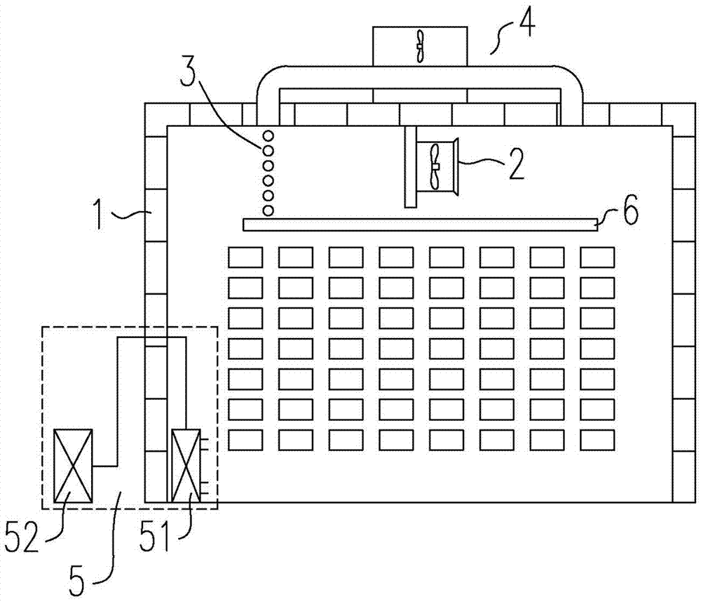
[0023] Embodiment 1: as figure 1 The shown active wood drying equipment includes a kiln body 1, a fan 2, a heating device 3 and a partition 6. The top of the kiln body 1 is provided with a passive dehumidification device 4, and the bottom of the kiln body 1 is provided with an active dehumidification device 5.

[0024] Kiln body 1

[0025] Because it is an improved structure of the existing drying kiln structure, the technical solution can be applied to various existing kiln body structures, such as brick kiln structure kiln body or aluminum alloy structure kiln body.

[0026] fan 2

[0027] The arrangement of fans includes top fan type, side fan type and end fan type. In this technical solution, considering its cooperation with passive dehumidification device 4 and active dehumidification device 5, the top fan type is the best choice, namely The fan 2 is located on the top of the kiln body 1 of the drying kiln.

[0028] Heating device 3

[0029] Those of ordinary skill in...

Embodiment 2

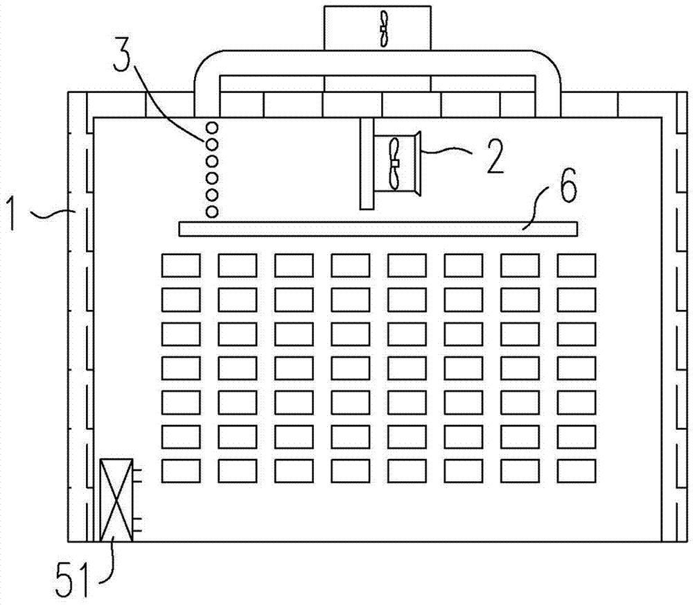
[0038] Embodiment 2: the difference between embodiment 2 and embodiment 1 is, as image 3 As shown, the active dehumidification device 5 is an integrated dehumidifier, which only forms an active dehumidification part 51 in the kiln body 1 . Optional dehumidifiers include compressor-type inverter dehumidifiers, with a daily dehumidification capacity of 25L / day and an applicable area of ​​about 80㎡.

Embodiment 3

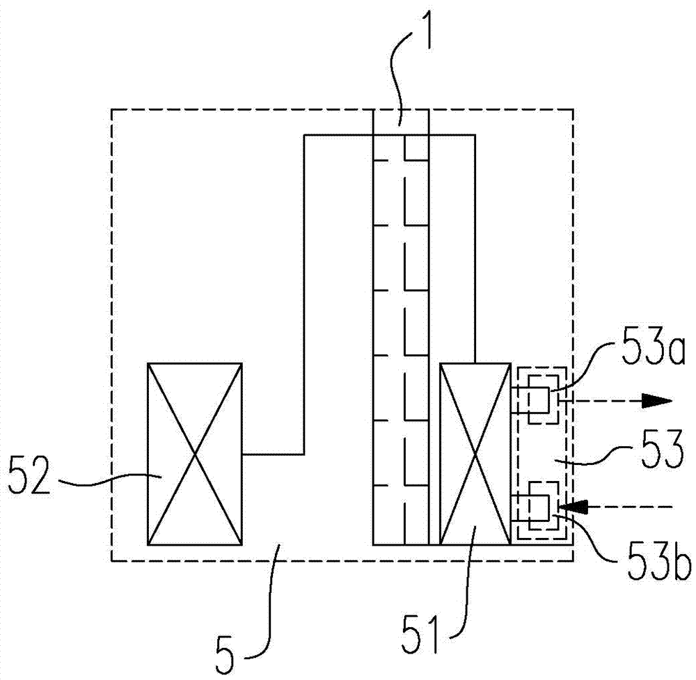
[0039] Embodiment 3: the difference between embodiment 3 and embodiment 1 is, as image 3 As shown, the active dehumidification unit 51 is located outside the kiln body 1 and processes the drying medium inside the kiln body 1 through the dehumidification pipeline 7 and the discharge pipeline 8 . The dehumidification pipeline 7 forms a dehumidification point 53a in the kiln body 1, which is used to pump the hot and humid drying medium into the active dehumidification part 51 and treat it; the discharge pipeline 8 forms a discharge point 53b in the kiln body 1, which is used to actively dehumidify the The dry and cold air treated by the section 51 is discharged back to the inside of the kiln body 1 . The advantage of placing it outside is that the dry medium sent back to the inside of the kiln body 1 is dry and cold medium, and its temperature is lower than that of the dry medium in the kiln body 1. This method is beneficial to the cooling process and drying in the cooling stage...


PUM


Abstract

The application discloses an active wood drying device comprising a kiln body, a fan and a heating device, wherein the top of the kiln body is provided with a passive dehumidification device; the active wood drying device also comprises an active dehumidification device which at least comprises an active dehumidification part arranged in the kiln body. The drying efficiency can be improved greatly, the drying cycle is shortened, and the drying energy consumption is reduced.

Description

technical field [0001] The application relates to the field of wood drying equipment, in particular to equipment that actively dries and realizes high-efficiency and high-quality drying. Background technique [0002] Wood is the only renewable material among the four basic raw materials. It has the characteristics of fast regeneration, natural, environmental protection and excellent performance. Wood runs through all aspects of human life with its irreplaceable functions. The drying treatment of wood is almost the longest and most energy-consuming process in the wood processing and manufacturing process, especially the existing drying process mostly uses high temperature and high humidity drying methods. For example, Chinese patent CN 103017485A discloses a high-temperature, high-humidity rapid drying process for wood, which includes: a step of humidifying and heating up, placing the wood in a drying kiln and closing the kiln door, opening the humidifying valve to quickly hu...

Claims


Application Information

Patent Timeline
IPC IPC(8): F26B9/06F26B21/04F26B21/08
CPCF26B9/06F26B21/04F26B21/086F26B2210/16
Inventor 彭冲卢俊梁锐维
Owner 清远市慧邦木业科技有限公司
Why Eureka
Try Eureka