High Q-value resonance magnetic sensor employing frequency conversion output
A magnetic sensor and frequency conversion technology, which is applied in the direction of magnetic field measurement and magnetic field size/direction by using electromagnetic devices, can solve the problem of high-precision detection of limited magnetic field frequency changes, high mechanical damage of magnetostrictive materials, and low frequency response sensitivity and other issues to achieve the effect of low cost, small size and fast response
- Summary
- Abstract
- Description
- Claims
- Application Information
AI Technical Summary
Problems solved by technology
Method used
Image
Examples
Embodiment 1
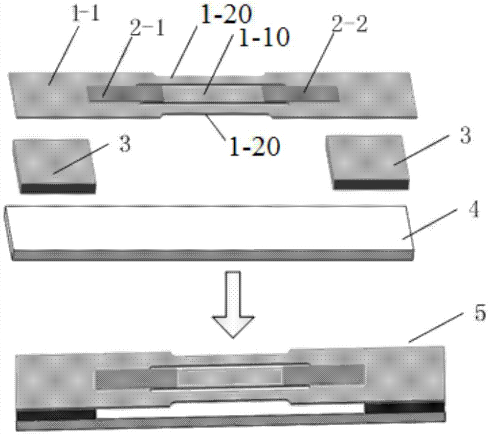
[0023] combine figure 1 , in this embodiment, the high-Q resonator in the magnetic sensitive unit 5 is a three-beam resonator, and the magnetic sensitive unit 5 shown includes a three-beam resonant structure 1-1, a piezoelectric drive unit 2-1, a piezoelectric detection Unit 2-2, resonator holder 3 and magnetostrictive unit 4.
[0024] The three-beam resonant structure 1-1 shown is essentially a tuning fork, which is an integrated sheet structure and can be made of low-loss elastic materials such as Si and elastic steel. The three-beam resonant structure 1 has three vibrating beams fixed at both ends, such as figure 1In the middle beam 1-10 and the two side beams 1-20, the width of the middle beam 1-10 is approximately twice the width of the side beams 1-20. In the optimized vibration mode, the vibration direction of the middle beam 1-10 is opposite to that of the two side beams 1-20, so that the bending moments and shear forces of the middle beam 1-10 and the two side beams...
Embodiment 2
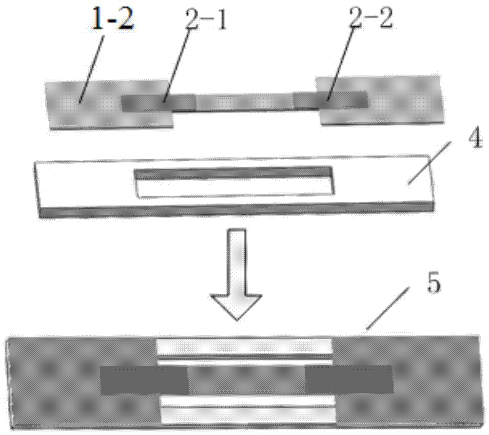
[0027] combine figure 2 , in this embodiment, the high-Q resonator in the magnetic sensitive unit 5 is a single beam resonator, and the magnetic sensitive unit 5 shown includes a single beam resonant structure 1-2, a piezoelectric drive unit 2-1, a piezoelectric detection unit Unit 2-2 and magnetostrictive unit 4. The single-beam resonant structure 1-2 has only one vibrating beam, the piezoelectric drive unit 2-1 and the piezoelectric detection unit 2-2 are compounded at both ends of the beam, and the upper and lower surfaces have electrodes, and the lower electrode is the electrode in contact with the beam . In this embodiment, the magnetostrictive unit 4 is a hollow structure, and the two ends of the vibration beam of the single-beam resonant structure 1-2 are directly compounded on the magnetostrictive unit 4 of the hollow structure, and the position of the vibration beam corresponds to the hollow structure, forming a vibration The beam is fixed at both ends and suspende...
Embodiment 3
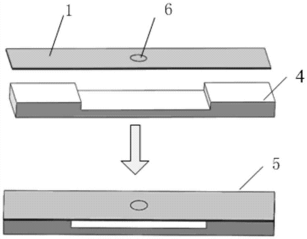
[0029] combine image 3 , in this embodiment, the high-Q resonator in the magnetic sensitive unit 5 is a quartz resonator, and the magnetic sensitive unit 5 shown includes a quartz resonant structure 1-3 and a magnetostrictive unit 4 . The quartz resonant structure 1-3 is a rectangular quartz crystal sheet, and electrodes 6 are symmetrically plated in the middle of its upper and lower surfaces (the electrodes on the lower surface are not shown). When voltage excitation is applied to the electrodes 6 on the upper and lower surfaces, the quartz crystal resonates, and due to the energy limit theory, the vibration of the quartz crystal is limited within the range of the electrodes and has a high Q value. For example, if the quartz crystal adopts an AT cut shape, the electrodes 6 on the upper and lower surfaces will vibrate in thickness shear under voltage excitation, and the resonant frequency in this vibration mode is sensitive to the longitudinal magnetostrictive stress. In thi...
PUM
 Abstract
Description
Claims
Application Information
 - R&D
- Intellectual Property
- Life Sciences
- Materials
- Tech Scout
- Unparalleled Data Quality
- Higher Quality Content
- 60% Fewer Hallucinations
Browse by: Latest US Patents, China's latest patents, Technical Efficacy Thesaurus, Application Domain, Technology Topic, Popular Technical Reports.
© 2025 PatSnap. All rights reserved.Legal|Privacy policy|Modern Slavery Act Transparency Statement|Sitemap|About US| Contact US: help@patsnap.com


