
Infrared signal detection circuit

A technology for detecting circuits and infrared signals, applied in signal transmission systems, non-electrical signal transmission systems, instruments, etc., can solve problems such as dynamic response errors, achieve good signal-to-noise ratio, high sensitivity and stability, and compact circuit structure Effect

Inactive Publication Date: 2017-06-20
韩会义
View PDF0 Cites 2 Cited by
  • Summary
  • Abstract
  • Description
  • Claims
  • Application Information

AI Technical Summary

Problems solved by technology

In the field of weapons, the transient temperature changes quickly with time, often on the order of microseconds. The thermal inertia and limited heat conduction of the temperature sensor make the measured temperature and the actual temperature have a dynamic response error.

Method used


Image

  • Infrared signal detection circuit
  • Infrared signal detection circuit
  • Infrared signal detection circuit

Examples


Embodiment Construction

[0016] The present invention will be further described below in conjunction with drawings and embodiments.

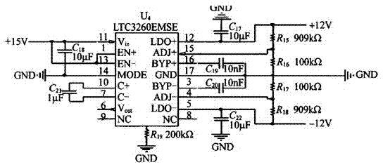
[0017] Such as figure 1 , The power supply circuit uses a DC-DC conversion chip, and the LTC3260 can convert the +15V voltage into ±12V to power the amplifier. In the preamplifier circuit, the DC power supply will generate clutter and ripple, as well as common-mode voltage that may be coupled to the power supply. These pulsating noises are on the order of microvolts and will affect useful signals.

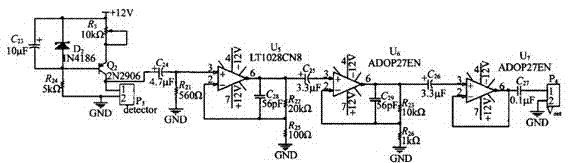
[0018] Such as figure 2 , In the bias circuit, electronic crosstalk can be eliminated by increasing the bias resistor. The output signal and noise of the infrared detector will change with the magnitude of the bias current. There is an optimal bias range, so that the output signal-to-noise ratio reaches the maximum value. The optimal bias current of the infrared detector in the system is 2mA ~ 4mA. This circuit utilizes the characteristics of the transistor to realize th...


PUM


Abstract

An infrared signal detection circuit relates to an infrared signal detection circuit, which is suitable for the field of temperature sensor calibration. The infrared signal detection circuit is composed of a power supply circuit, a bias circuit and an amplifier circuit. The circuit utilizes the characteristics of the transistor to realize the constant current bias and form the transistor constant current bias circuit by utilizing the characteristic that the equivalent AC resistance of the transistor is very large when it works in the linear region, and it is similar to the characteristics of a constant current source. The circuit structure is compact, has good signal-to-noise ratio, can amplify weak signals, and has high sensitivity and stability.

Description

[0001] Technical field [0002] The invention relates to an infrared signal detection circuit, which is suitable for the field of temperature sensor calibration. Background technique [0003] With the increasing demand for transient temperature testing, the dynamic characteristics of temperature sensors have become the focus of researchers. In the field of weapons, the transient temperature changes rapidly with time, often on the order of microseconds. The thermal inertia and limited heat conduction of the temperature sensor cause a dynamic response error between the measured temperature and the actual temperature. In order to reduce this kind of error, the temperature sensor needs to be calibrated dynamically to compensate for the existing dynamic error. The HgCdTe photoconductive infrared detector is a key component of the traceable dynamic calibration system. Its peak detection rate is not less than 5x10⁹ cmHz1 / 2 W-1, and its response rate is 1us faster than the temperatur...

Claims


Application Information

Patent Timeline
IPC IPC(8): G08C23/04G08C25/00
CPCG08C23/04G08C25/00
Inventor 韩会义
Owner 韩会义
Features
  • Generate Ideas
  • Intellectual Property
  • Life Sciences
  • Materials
  • Tech Scout
  • Unparalleled Data Quality
  • Higher Quality Content
  • 60% Fewer Hallucinations
Learn More