Adjustable bandstop filter

A band-stop filter and filter technology, which is applied in waveguide devices, electrical components, circuits, etc., can solve the problems of difficult integration of wireless communication terminal equipment, narrow working bandwidth of band-stop filters, and relatively high processing technology requirements. Achieve the effect of reducing unnecessary coupling, taking into account compactness and integrity, and reducing signal interference

Active Publication Date: 2020-08-11
UNIV OF ELECTRONIC SCI & TECH OF CHINA
View PDF8 Cites 0 Cited by
  • Summary
  • Abstract
  • Description
  • Claims
  • Application Information

AI Technical Summary

Problems solved by technology

However, the working bandwidth of the band-stop filter is relatively narrow, and the processing technology requirements are relatively high. Once the precision control deviates, the working frequency is easy to shift
In addition, compared with chip-level multilayer circuit components, the size of the filter is still large, and it is difficult to integrate in increasingly miniaturized wireless communication terminal equipment
The document with the application number 201410290334.7 discloses an ultra-wideband band-stop filter based on multi-step impedance resonator loa

Method used


Image

  • Adjustable bandstop filter
  • Adjustable bandstop filter
  • Adjustable bandstop filter

Examples


Embodiment

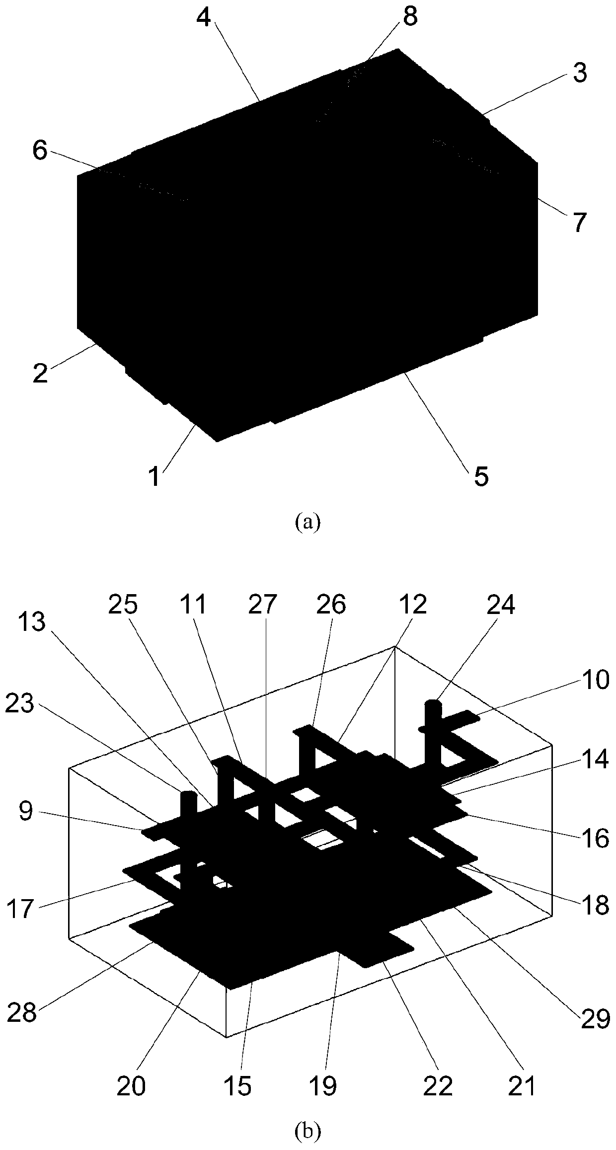
[0061] Please refer to Figure 1 to Figure 10 The adjustable band-rejection filter described in this embodiment includes a band-rejection filter main body 1 with a main circuit inside; a tuning element 8 is arranged outside the band-stopping filter main body 1, and the tuning element 8 is electrically connected to the main circuit. To change the transmission zero point of the main circuit.

[0062] In this embodiment, both the main circuit and the tuning element 8 are arranged in a multi-layer structure. Both the main circuit and the tuning element 8 are manufactured based on the low-temperature co-fired ceramic (LTCC) process. Based on the low-temperature co-fired ceramic process, various passive devices are buried in the ceramic medium, and various equivalent components are realized on the three-dimensional circuit substrate. Integration, miniaturization and high density of the circuit. Metal materials with high electrical conductivity, such as silver and copper, can be us...


PUM

PropertyMeasurementUnit
Capacitanceaaaaaaaaaa

Abstract

The invention discloses an adjustable bandstop filter, and relates to the technical field of microwave communication. The adjustable bandstop filter comprises a bandstop filter main body internally provided with a main body circuit, wherein the main body circuit is electrically connected with a plurality of electrodes, the electrodes are arranged outside the bandstop filter main body, a tuning element is arranged outside the bandstop filter main body, is electrically connected with the main body circuit and is used for changing a transmission zero point of the main body circuit, and the main body circuit is manufactured based on a low-temperature co-fired ceramic process. According to the invention, the adjustable bandstop filter is small in size, and based on the low-temperature co-firedceramic technology, the circuit of the filter is compact in structure and good in repeatability; the stop band width and the in-band rejection depth are flexibly adjustable, and the transmission zeropoint position of the bandstop filter can be reset by changing the value of an external tuning element, so that the filter can be conveniently switched between wide stop band and high rejection in different required environments; the insertion loss is small; and the filter achieves a high suppression level in a small size, and can effectively filter out various useless signals and noise signals.

Description

technical field [0001] The invention relates to the technical field of microwave communication, in particular to an ultra-small adjustable band-stop filter. Background technique [0002] The traditional band-stop filter design structure is generally composed of quarter-wavelength stub resonators, which are arranged along the main waveguide or main transmission line, and the interval between the resonators is an odd multiple of the quarter-wavelength. The square coefficient of the reject filter is not ideal and bulky. In recent years, with the emergence of new materials and process technologies such as micro-electromechanical systems (MEMS) technology, high-temperature superconducting technology, low-temperature co-fired ceramics (LTCC) technology, photonic bandgap structure, and microwave monolithic integrated circuits, the filter Continuous improvement from performance to volume. With the continuous development of wireless communication systems and microwave and millimete...

Claims


Application Information

Patent Timeline
IPC IPC(8): H01P1/203
CPCH01P1/203
Inventor 钱可伟田忠
Owner UNIV OF ELECTRONIC SCI & TECH OF CHINA
Why Eureka
Try Eureka