Switched reluctance motor dual-PWM power converter

A switched reluctance motor and power converter technology, applied in the direction of converting AC power input to AC power output, AC power input converting to DC power output, and output power conversion devices, etc., can solve the problem of low system power factor and DC busbar. Insufficient voltage, low energy consumption of switched reluctance motor, etc., to achieve the effect of no harmonic pollution and bidirectional power flow

Inactive Publication Date: 2017-06-20
STATE GRID JIANGSU ELECTRIC POWER CO LTD MAINTENANCE BRANCH +2
View PDF4 Cites 3 Cited by
  • Summary
  • Abstract
  • Description
  • Claims
  • Application Information

AI Technical Summary

Problems solved by technology

[0002] The switched reluctance motor speed control system has the advantages of high efficiency and high performance. At present, the front-end rectification of the switched reluctance motor power converter is realized by uncontrollable diode rectification. Not only the system power factor is low, but also the harmonics of the input current Larger, the DC bus voltage is not enough
In addition, due to the unidirectional conductivity of the diode, the traditional power converter cannot realize the bidirectional flow of energy. When the motor is in the braking operation state, it is necessary to configure a bulky braking resistor to consume the electric energy generated by the motor, resulting in the switching magnetic The overall system efficiency of the resistance motor is low and the energy consumption is serious, so the traditional power converter limits the high performance advantages of the switched reluctance motor

Method used


Image

  • Switched reluctance motor dual-PWM power converter
  • Switched reluctance motor dual-PWM power converter

Examples


Embodiment Construction

[0018] The present invention will be further described below in conjunction with the accompanying drawings. The following examples are only used to illustrate the technical solution of the present invention more clearly, but not to limit the protection scope of the present invention.

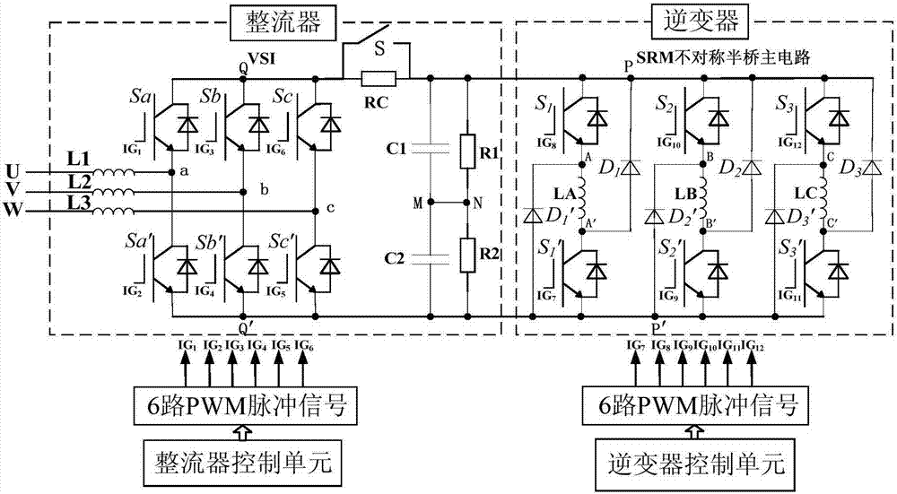
[0019] Such as figure 1 As shown, a switched reluctance motor dual PWM power converter includes an IGBT rectifier, a rectifier control unit, an inverter and an inverter control unit.

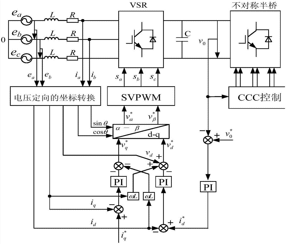
[0020] The input end of the IGBT rectifier is connected to an external AC power, the output end of the IGBT rectifier is connected to the input end of the inverter, the output end of the inverter is connected to the winding of the switched reluctance motor, and the rectifier control unit adopts a voltage-oriented vector control strategy to output control to the IGBT rectifier Pulse, the inverter control unit adopts the current chopper control strategy to output control pulses to the inverter.

[0021] The above-...


PUM


Abstract

The invention discloses a double-PWM power converter for a switched reluctance motor, comprising an IGBT rectifier, a rectifier control unit, an inverter and an inverter control unit; The input end of the inverter is connected, the output end of the inverter is externally connected to the winding of the switched reluctance motor, the rectifier control unit adopts a voltage-oriented vector control strategy, and outputs control pulses to the IGBT rectifier, and the inverter control unit adopts a current chopping control strategy, Output control pulses to the inverter. The present invention adopts a voltage-oriented vector control strategy on the rectification side, and a current chopping control strategy on the inverter side. The rectification and inverter constitute a dual-PWM switched reluctance motor power converter, which realizes bidirectional flow of power and does not generate harmonics to the power grid. Wave pollution, so it is a truly green and efficient power electronic device.

Description

technical field [0001] The invention relates to a power converter, in particular to a dual-PWM power converter for a switched reluctance motor. Background technique [0002] The switched reluctance motor speed control system has the advantages of high efficiency and high performance. At present, the front-end rectification of the switched reluctance motor power converter is realized by uncontrollable diode rectification. Not only the system power factor is low, but also the harmonics of the input current Larger, the DC bus voltage is not enough. In addition, due to the unidirectional conductivity of the diode, the traditional power converter cannot realize the bidirectional flow of energy. When the motor is in the braking operation state, it is necessary to configure a bulky braking resistor to consume the electric energy generated by the motor, resulting in the switching magnetic The overall system efficiency of the resistance motor is low and the energy consumption is ser...

Claims


Application Information

Patent Timeline
Patent Type & Authority Applications(China)
IPC IPC(8): H02M5/458H02M7/219H02M7/5387
CPCH02M5/4585H02M7/219H02M7/5387
Inventor 王鹏飞张郭晶黄厚明陈晓贵江渭涛蒋政赵宏飞张飞宇王怀兵
Owner STATE GRID JIANGSU ELECTRIC POWER CO LTD MAINTENANCE BRANCH
Why Eureka
Try Eureka