Convex plate clamping device

A technology of clamping device and boss, which is applied in the field of mechanical processing, can solve problems such as complex structure and difficulty in sequential completion, and achieve the effects of good reliability, prolonging service life and reducing wear

Inactive Publication Date: 2017-06-23
ZHEJIANG HONGFENG WARP & WEFT KNITTING
View PDF0 Cites 2 Cited by
  • Summary
  • Abstract
  • Description
  • Claims
  • Application Information

AI Technical Summary

Problems solved by technology

These actions need to be carried out step by step to facilitate the loading, processing and unloading of the boss, but the structure of the current clamping device for the boss is relatively complicated, and it is difficult to complete these actions in sequence

Method used


Image

  • Convex plate clamping device
  • Convex plate clamping device

Examples


Embodiment Construction

[0012] The present invention will be further described in detail below in conjunction with the accompanying drawings and examples. The following examples are explanations of the present invention and the present invention is not limited to the following examples.

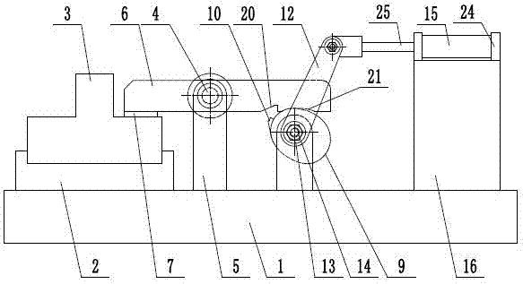
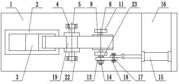
[0013] Such as figure 1 and figure 2 As shown, a boss clamping device includes a frame 1, a support base 2, a boss 3, a fulcrum 4, a fulcrum support 5, a pressure plate 6, a pressure head 7, a camshaft 8, a cam 9, a cam Claw 10, cam support 11, rocker 12, washer 13, lock nut 14, drive cylinder 15, cylinder support 16, support pin 17, adjustment nut 18, the support base 2 is fixed on the left side of the frame 1 side, the boss 3 is installed on the support base 2, the support shaft 4 is a stepped shaft, the diameter of the middle end of the support shaft 4 is larger than the diameter of both ends, and the middle end of the support shaft 4 is provided with a rectangular groove 19, so The two ends of the fulcrum 4 a...


PUM


Abstract

The invention provides a boss clamping device, which belongs to the technical field of mechanical processing. It includes a pressure plate, a cam, a claw, and a rocker. The fulcrum is a stepped shaft. The diameter of the middle end of the fulcrum is larger than the diameter of both ends. On the support, the pressure plate passes through the rectangular groove at the middle end of the support shaft, the pressure head is set at the lower left end of the pressure plate, and the lower side of the right end of the pressure plate is also provided with a transverse groove and a cam support groove, and the cam is fixedly installed on the camshaft, and the cam and the cam of the pressure plate The supporting groove fits together, and the side of the cam is also equipped with a claw that matches the shape of the transverse groove. The lower end of the rocker is installed on the camshaft through a lock nut, and the left end of the piston rod that drives the cylinder and the upper end of the rocker pass through the support pin. Shaft hinged. The present invention sequentially realizes that the pressing plate advances, then clamps the hem, then lifts and releases, and finally completes the retreat action, which is beneficial to the feeding, processing and unloading of the boss, and has reasonable structure, low cost and good reliability.

Description

technical field [0001] The invention relates to the technical field of machining, in particular to a boss clamping device. Background technique [0002] Machining refers to the process of changing the shape or performance of a workpiece through a mechanical device. According to the difference in processing methods, it can be divided into cutting processing and pressure processing. The machinery required for processing consists of digital display milling machine, digital display forming grinder, digital display lathe, EDM machine, universal grinding machine, machining center, drilling machine, laser welding, fast wire walking, medium wire walking, slow wire walking, outer cylindrical grinder, inner circle Grinding machines, precision lathes, etc. Cutting processing refers to the processing method of using cutting tools (including cutting tools, grinding tools and abrasives) to cut off the excess material layer on the blank or workpiece into chips, so that the workpiece can o...

Claims


Application Information

Patent Timeline
Patent Type & Authority Applications(China)
IPC IPC(8): B23Q3/08
CPCB23Q3/08
Inventor 曹建栋
Owner ZHEJIANG HONGFENG WARP & WEFT KNITTING
Why Eureka
Try Eureka