Multi-functional unmanned aerial vehicle intelligent take off and land station system

A multi-functional, unmanned aerial vehicle technology, applied in the field of unmanned aerial vehicles, can solve problems such as difficult to reach, time-consuming and costly, and achieve the effect of improving efficiency and accuracy, ensuring accuracy, and improving capabilities

Active Publication Date: 2017-06-23
SHANDONG UNIV +1
View PDF6 Cites 16 Cited by
  • Summary
  • Abstract
  • Description
  • Claims
  • Application Information

AI Technical Summary

Problems solved by technology

Therefore, one drone operation is time-consuming and labor-intensive, especially for occasions that require high-frequency drone operations, the cost is particularly high, and the harsh terrain is difficult to reach
[0004] Battery development restricts the battery life of drones; drones cannot be done once and for all, and each task needs to be calibrated; each operation requires the cooperation of multiple people to complete smoothly; Some harsh terrains that are difficult for vehicles to reach require people to climb to the collection site to achieve the best collection effect; for occasions that require high-frequency operations, the disadvantages are particularly prominent
Similarly, the endurance problem that restricts the large-scale application of multi-rotor UAVs has not been resolved so far.

Method used


Image

  • Multi-functional unmanned aerial vehicle intelligent take off and land station system
  • Multi-functional unmanned aerial vehicle intelligent take off and land station system
  • Multi-functional unmanned aerial vehicle intelligent take off and land station system

Examples


Embodiment Construction

[0041] It should be pointed out that the following detailed description is exemplary and intended to provide further explanation to the present application. Unless defined otherwise, all technical and scientific terms used herein have the same meaning as commonly understood by one of ordinary skill in the art to which this application belongs.

[0042] It should be noted that the terminology used here is only for describing specific implementations, and is not intended to limit the exemplary implementations according to the present application. As used herein, unless the context clearly dictates otherwise, the singular is intended to include the plural, and it should also be understood that when the terms "comprising" and / or "comprising" are used in this specification, they mean There are features, steps, operations, means, components and / or combinations thereof.

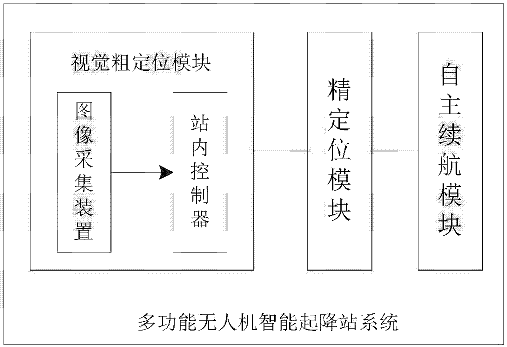
[0043] figure 1 It is a structural schematic diagram of a multifunctional unmanned aerial vehicle intelligent t...


PUM


Abstract

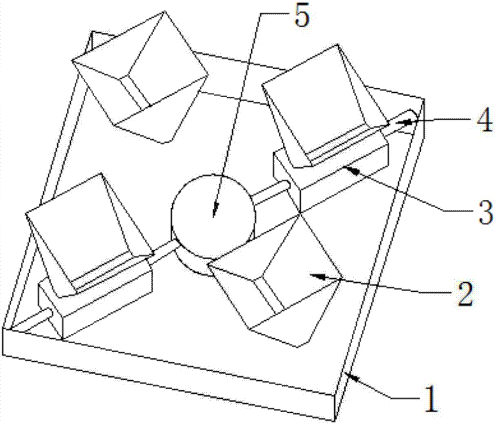
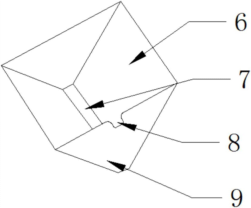
The invention discloses a multi-functional unmanned aerial vehicle intelligent take off and land station system which comprises a visual coarse positioning module. The visual coarse positioning module comprises an instation controller which is connected with an image acquisition device. The image acquisition device is arranged in a take off and land station and is used for acquiring an unmanned aerial vehicle image in real time, and transmitting the image to the instation controller. An airborne controller controls the landing height of an unmanned aerial vehicle and the head direction of the unmanned aerial vehicle. The system further comprises a fine positioning module which comprises a support frame which is used for carrying the unmanned aerial vehicle. Grooves which match rotors of the unmanned aerial vehicle are arranged on the support frame. A notch is arranged on the side, which contacts the unmanned aerial vehicle support frame, of each groove. The notches are used for supporting and fixing the unmanned aerial vehicle. The system further comprises a self-sustaining module which is used for receiving the electric quantity information and the battery position information, which are transmitted from the airborne controller, of an unmanned aerial vehicle battery compartment, and charging the unmanned aerial vehicle battery compartment lower than or equal to the preset electric quantity information to realize self-sustaining of the unmanned aerial vehicle.

Description

technical field [0001] The invention belongs to the field of unmanned aerial vehicles, and in particular relates to a multifunctional unmanned aerial vehicle intelligent landing station system. Background technique [0002] With the continuous development and promotion of drones, the application fields are gradually widening, such as agricultural spraying, power inspection, disaster prevention and emergency response, aerial photography mapping and relay communication fields. Moreover, ground equipment has become the key to the safe, stable and efficient operation of the whole set of drones. [0003] At present, the main form of UAV application is to use the remote control to control the UAV by professional pilots on the spot, and at the same time, a few staff members are equipped to observe the flight status of the UAV, change the battery for the UAV, and observe the data collected by the UAV. Quality, etc., to ensure that drones complete tasks safely and efficiently. Ther...

Claims


Application Information

Patent Timeline
Patent Type & Authority Applications(China)
IPC IPC(8): G05D1/10G05B19/04G06T7/73G06T7/13G06T7/11G06T7/194G06T7/143G06T7/168
CPCG05B19/04G05D1/101G06T2207/10004G06T2207/20061
Inventor 马思乐马晓静孙文旭王军峰王兴元丁为飞孙景余张佰顺陈祥海丁为杰陈远方赵月李金刚王勇
Owner SHANDONG UNIV
Why Eureka
Try Eureka