LED lighting heat sink and method for manufacturing same

A technology of LED lighting and cooling fins, which is applied in lighting and heating equipment, cooling/heating devices of lighting devices, lighting devices, etc., can solve the problems of high manufacturing costs, complex molds, and needs, so as to reduce manufacturing costs and realize Part structure, effect of high dimensional accuracy

Inactive Publication Date: 2017-06-27
KOBE STEEL LTD
View PDF17 Cites 0 Cited by
  • Summary
  • Abstract
  • Description
  • Claims
  • Application Information

AI Technical Summary

Problems solved by technology

[0014] However, when attempting to manufacture die-cast heat sinks made of aluminum or an aluminum alloy as described above, the manufacturing cost increases and the heat sink becomes heavier.
Not suitable for use as a heat sink for LED bulbs especially in heavier cases
In addition, in the case of forming many fins on the surface and processing it into a complicated shape, there is also a problem that a mold with a complicated shape is required
[0015] As such, heat sinks with an aluminum die-cast structure are not only heavy, but also have the problem of high manufacturing costs, so studies have been made to manufacture heat sinks using metal plates such as aluminum or aluminum alloys.
However, it is difficult to form the mounting portion for mounting the LED substrate with only one sheet
As a result, there is a problem that many parts are required, the number of parts is increased, and many parts need to be assembled. From this point of view, the manufacturing cost is also increased.

Method used


Image

  • LED lighting heat sink and method for manufacturing same
  • LED lighting heat sink and method for manufacturing same
  • LED lighting heat sink and method for manufacturing same

Examples


no. 3 approach

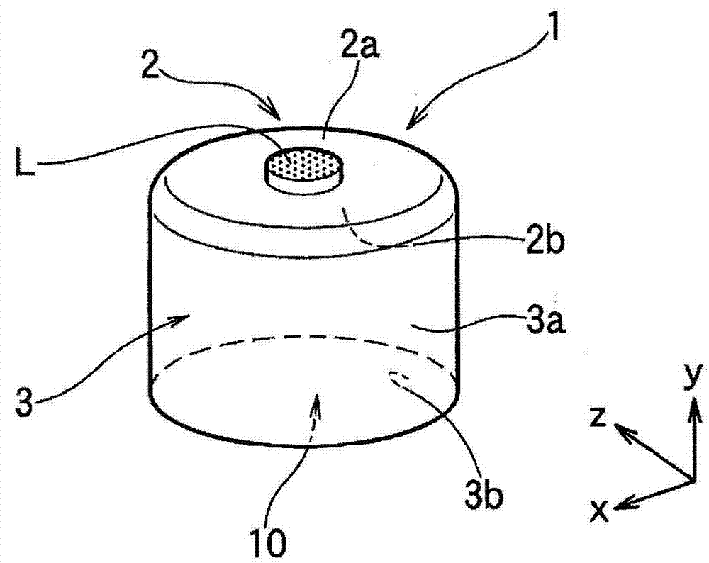
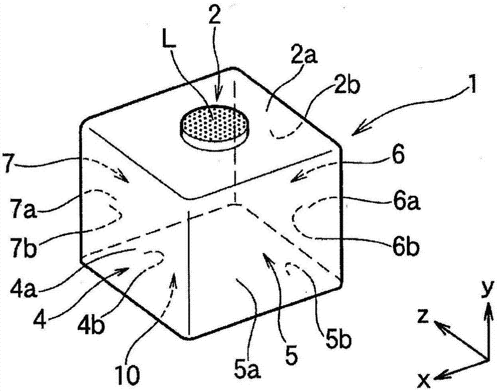
[0110] image 3 A third embodiment of the heat sink for LED lighting according to the present invention is shown. image 3 Heat sink 1 shown for LED lighting with figure 2 Similarly, a metal thin plate 1 having a constant plate thickness such as aluminum is integrally formed, and as figure 2 Thus, the whole has a hollow square tube shape (square tube cup shape). figure 2 The heat sink 1 for LED lighting of the present invention is different from the above-mentioned point in that the LED element mounting surface 2 and the heat dissipation side surface 3 are integrally formed from a single metal sheet by drawing processing. figure 1 , 2 The situation is the same.

[0111] Should image 3 The heat sink 1 for LED lighting has an LED component mounting surface 2 and four heat dissipation side surfaces 4, 5, 6, and 7 that are planar, and is formed in the Y direction (up and down) of the drawings with a section higher than the LED component mounting surface 2. direction) and ...

no. 4 approach

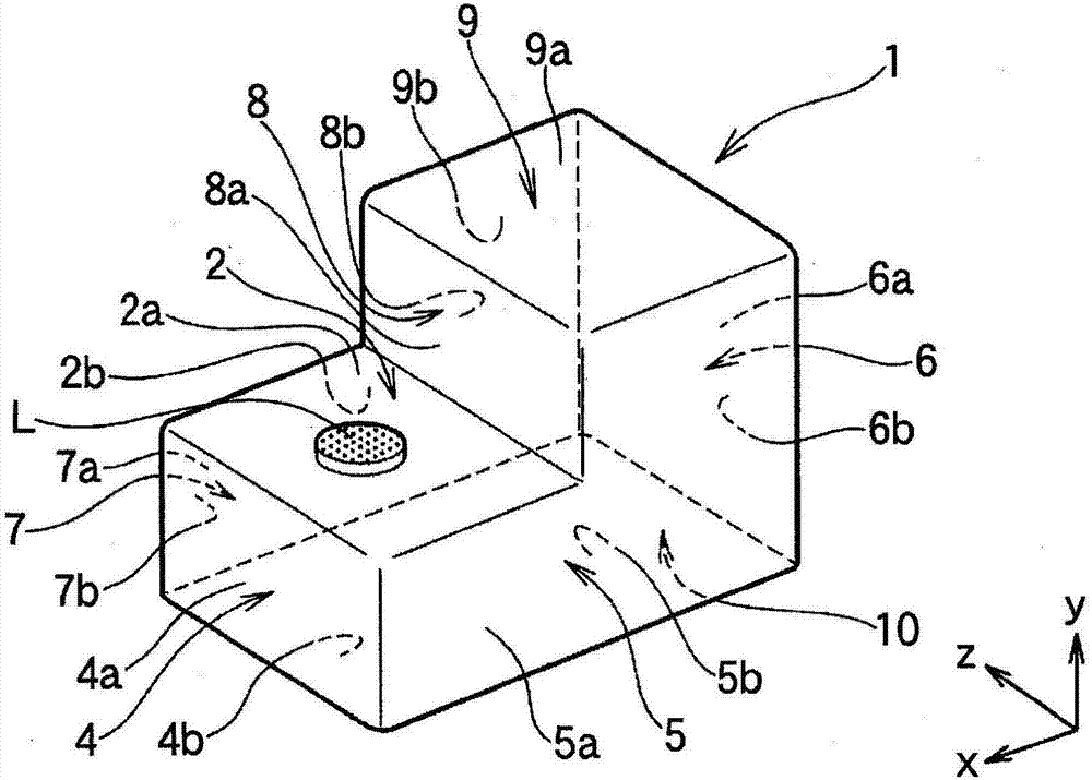
[0120] Figure 4 A fourth embodiment of the heat sink for LED lighting according to the present invention is shown. Figure 4 Heat sink 1 shown for LED lighting is with figure 2 Same overall shape, but no figure 2 Like the opening 10 on the bottom side, the heat dissipation side 6 in the cylinder has an opening (space) 11 in which the internal space of the cylindrical body is opened to the outside without actually having a heat dissipation side.

[0121] The opening 11 is provided within a range that does not hinder the rigidity of the heat sink 1 , and can have a larger area than the heat radiation side area of ​​the heat sink 1 in cooperation with the opening 10 on the bottom side. Therefore, the convection function between the air in the internal space and the outside air through the openings 10 and 11 inside and outside the heat sink 1 is improved. As a result, with figure 2 Compared with the case where the heat dissipation side surface 6 is not provided, the area o...


PUM


Abstract

The present invention relates to an LED lighting heat sink which is capable of being manufactured from an aluminum plate by a relatively simple processing method, and efficiently performs heat radiation even when applied to and installed in a closed space. The LED lighting heat sink according to the present invention is an LED lighting heat sink (1) where an LED element mounting surface (2) and a radiation side surface (3) are formed integrally or continuously on one sheet metal by drawing. The heat sink of the present invention comprises radiation surfaces in a continuous manner, which are formed on a cylindrical body to face any three-dimensional direction.

Description

[0001] This application is a divisional application of the application with the international application number PCT / JP2012 / 081769, the national phase application number 201280054494.0, the application date on December 7, 2012, and the invention title "Heat sink for LED lighting and its manufacturing method". technical field [0002] The present invention relates to a heat sink for LED lighting for dissipating the heat generated when LED lighting using light-emitting diode (LED) elements (including a structure in which a plurality of elements are mounted on a substrate or the like) as a light-emitting source to the surrounding space. piece. Background technique [0003] Lighting with light-emitting diode (LED) elements as light sources has gradually penetrated into the market due to its low power consumption and long life. Such LED lamps include ordinary bulb-type LED bulbs developed to replace existing bulbs such as incandescent lamps and fluorescent lamps, automotive LED l...

Claims


Application Information

Patent Timeline
Patent Type & Authority Applications(China)
IPC IPC(8): F21V29/70F21Y115/10
CPCF21V29/70F21Y2115/10F28D2021/0029F21V29/00
Inventor 小西晴之
Owner KOBE STEEL LTD
Why Eureka
Try Eureka