Supercharge Your Innovation With Domain-Expert AI Agents!

Cold supply system for water cold storage independent temperature and humidity control area

An independent control, temperature and humidity technology, applied in heating and ventilation control systems, heating and ventilation safety systems, energy recovery systems for ventilation and heating, etc., can solve problems such as easy breeding of bacteria, leakage of condensed water, waste of energy utilization, etc. , to achieve the effect of reducing the power consumption of the water pump, reducing the investment, and increasing the temperature difference between the chilled water supply and return water

Active Publication Date: 2017-06-27
SOUTHEAST UNIV
View PDF5 Cites 3 Cited by
  • Summary
  • Abstract
  • Description
  • Claims
  • Application Information

AI Technical Summary

Problems solved by technology

However, the sensible heat load, which accounts for more than half of the total load, could have been taken away by a high-temperature cold source, but it is treated with a 7°C low-temperature cold source together with dehumidification, resulting in a waste of energy utilization
At the same time, the system also has environmental problems such as condensate leakage and easy breeding of bacteria.
The second is to adopt the warm fresh air system. Although the heat and humidity are treated separately, which overcomes the shortcomings of the traditional cooling and condensation dehumidification fresh air treatment methods, it needs to use two sets of equipment to supply cooling separately.

Method used


Image

  • Cold supply system for water cold storage independent temperature and humidity control area
  • Cold supply system for water cold storage independent temperature and humidity control area

Examples


Embodiment Construction

[0028] The present invention will be further described below in conjunction with embodiment and accompanying drawing.

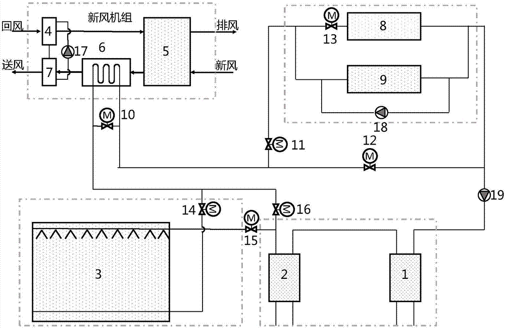
[0029] attached figure 1 It shows a water cold storage temperature and humidity independent control district cooling system, including a cold source system, a cold storage system, a fresh air system and an independent temperature control system. The cold source system includes a high-temperature chiller 1, a low-temperature chiller 2 and a cold storage pool 3. The chilled water outlet pipeline of the high-temperature chiller 1 is connected to the chilled water return pipeline of the low-temperature chiller 2 , and the chilled water outlet pipeline of the low-temperature chiller 2 is connected to the chilled water inlet pipeline of the cold storage tank 3 . The fresh air system includes a return air-water heat exchanger 4, a runner heat recovery device 5, a fresh air-water heat exchanger 6 and a supply air-water heat exchanger 7, and the inlet of the return ai...


PUM


Abstract

The invention discloses a cold supply system for a water cold storage independent temperature and humidity control area. The cold supply system is composed of a cold source system, a water cold storage system, a fresh air system, an independent temperature control system and the like. A water cooling unit system is composed of a high-temperature water cooling unit and a low-temperature water cooling unit. The fresh air system is composed of an air return-water heat exchanger, an air supply-water heat exchanger, a fresh air-water heat exchanger and a full heat recovery device. The independent temperature control system is composed of a dry fan coil and a radiation type tail end. The fresh air system and the independent temperature control system are connected in a series manner. The fresh air system is located at the upstream position of the independent temperature control system, low-temperature freeze water from a cold storage water pond passes through the fresh air system, then the temperature of the low-temperature freeze water is increased, and the low-temperature freeze water is sent to the independent temperature control system to be further utilized. By means of the cold supply system for the water cold storage independent temperature and humidity control area, gradient utilization of the refrigerating capacity is achieved, the defect that a traditional fan coil system is likely to be condensed is overcome, and the air quality is improved.

Description

technical field [0001] The invention belongs to the field of heating, ventilating and air-conditioning systems, and relates to a water cold storage temperature and humidity independent control area cooling system. Background technique [0002] In district cooling projects, due to the large diameter of the secondary pipe network, small flow of cold water, and high power of the secondary pump, the problems of high cost of the secondary pipe network and excessive energy consumption of the transmission and distribution system are common. When the cooling capacity delivered by the secondary pipe network is the same, the greater the temperature difference between the chilled water supply and return water, the smaller the chilled water flow. Within a certain flow rate range, the smaller the pipe diameter, the smaller the power of the secondary pump. Therefore, increasing the temperature difference between the system's supply and return water has become an important way to improve ...

Claims


Application Information

Patent Timeline
IPC IPC(8): F24F5/00F24F13/30F24F11/02F24F13/22F24F12/00
CPCF24F5/0017F24F11/89F24F12/002F24F13/22F24F13/30F24F2013/221Y02B30/70Y02E60/14
Inventor 经骏张伦张小松
Owner SOUTHEAST UNIV
Features
  • R&D
  • Intellectual Property
  • Life Sciences
  • Materials
  • Tech Scout
  • Unparalleled Data Quality
  • Higher Quality Content
  • 60% Fewer Hallucinations
Learn More