Preparation method of display substrate, array substrate and display apparatus

A technology for display substrates and array substrates, which is applied in semiconductor/solid-state device manufacturing, semiconductor devices, electrical components, etc., and can solve problems such as extension, cycle shortening, and long etching time

Active Publication Date: 2017-06-27
HEFEI XINSHENG OPTOELECTRONICS TECH CO LTD +1
View PDF3 Cites 10 Cited by
  • Summary
  • Abstract
  • Description
  • Claims
  • Application Information

AI Technical Summary

Problems solved by technology

Etch targets are usually oxides and / or nitrides (e.g. silicon oxide SiO x and / or silicon nitride SiN y ), when etching the area of ​​the insulating layer exposed by the photoresist, due to the large thickness of the film layer to be etched (thickness is generally above 400nm), the required etching time is longer, resulting in the photoresist The remaining part is bombarded by plasma for a long time in dry etching, which is easy to cause PR Burning (full name Photoresist Burning, that is, photoresist curing), and then wet etching is used to strip (Wet Strip) the photolithography remaining on the rest of the insulating layer. When glueing, there will be more Floating Particles (residual particles after the photoresist is cured) that cannot be stripped (stripped off) on the insulating layer; at the same time, the tact time (that is, the process time) of the dry etching equipment will be prolonged, A series of adverse effects such as the shortening of the PM (full name Periodic Maintenance) cycle required for the equipment chamber

Method used


Image

  • Preparation method of display substrate, array substrate and display apparatus
  • Preparation method of display substrate, array substrate and display apparatus
  • Preparation method of display substrate, array substrate and display apparatus

Examples


Embodiment Construction

[0036] The following will clearly and completely describe the technical solutions in the embodiments of the present invention with reference to the accompanying drawings in the embodiments of the present invention. Obviously, the described embodiments are only some, not all, embodiments of the present invention. Based on the embodiments of the present invention, all other embodiments obtained by persons of ordinary skill in the art without making creative efforts belong to the protection scope of the present invention.

[0037] It should be noted that, unless otherwise defined, all terms (including technical and scientific terms) used in the embodiments of the present invention have the same meaning as commonly understood by those of ordinary skill in the art to which the present invention belongs. It should also be understood that terms such as those defined in common dictionaries should be interpreted as having meanings consistent with their meanings in the context of the relev...


PUM

PropertyMeasurementUnit
thicknessaaaaaaaaaa
thicknessaaaaaaaaaa
thicknessaaaaaaaaaa

Abstract

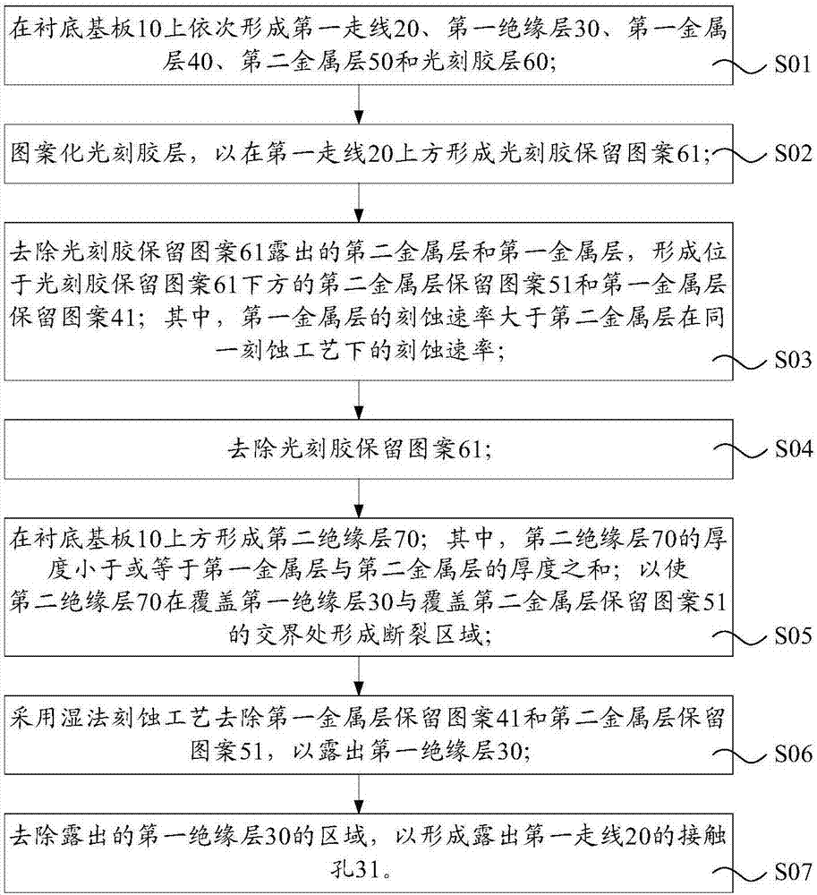
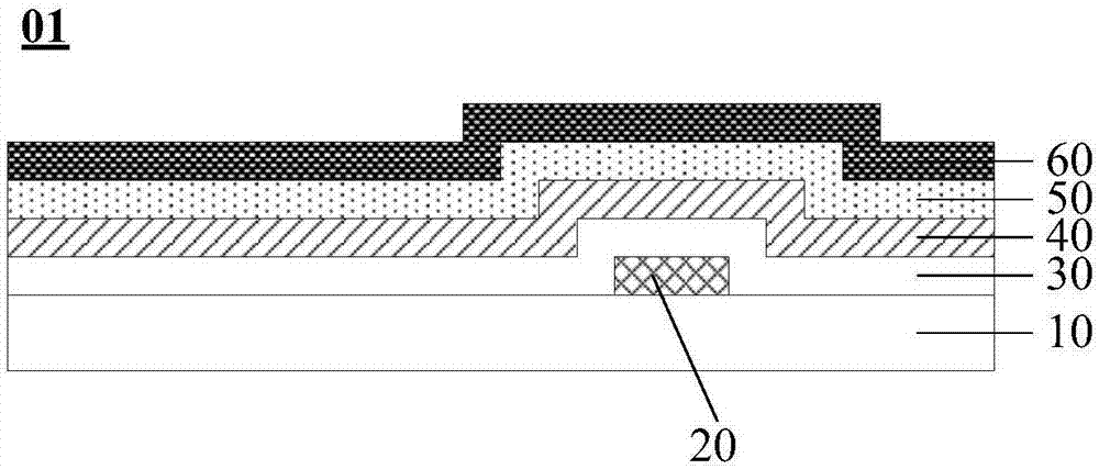
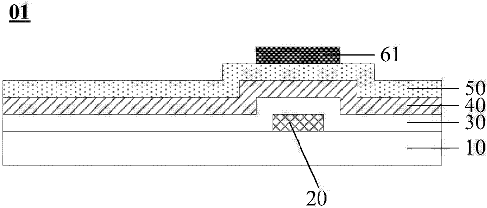
The embodiment of the invention provides a preparation method of a display substrate, an array substrate and a display apparatus, and relates to the technical field of display, solving the problem that a traditional contact hole process can cause solidification of photoresist, particle residue; the process time is prolonged; and the equipment maintenance period is shortened. The preparation method of a display substrate includes the steps: forming first wiring, a first insulating layer, first and second metal layers, and a photoresist layer; forming a photoresist reservation pattern above the first wiring; forming second and first metal layer reservation patterns below the photoresist reservation pattern, wherein the etching rate of the first metal layer is greater than the etching rate of the second metal layer; removing the photoresist reservation pattern; forming a second insulating layer, wherein the thickness of the second insulating layer is equal to the sum of the thickness of the first and second metal layers; and the second insulating layer is provided with a fracture area at the juncture covering the first insulating layer and the second metal level reservation pattern; utilizing a wet etching process to remove the first and second metal level reservation patterns to expose the first insulating layer; and forming a contact hole exposing the first wiring.

Description

technical field [0001] The invention relates to the field of display technology, in particular to a method for preparing a display substrate, an array substrate and a display device. Background technique [0002] Dry etching (Dry Etch) is to use high-energy plasma to hit the surface of the film to etch the film. It is widely used in the manufacturing fields of semiconductors and flat panel displays. [0003] The existing field of display panel preparation involves the process of forming a contact hole (full name contact, abbreviated as CNT) on the insulating layer. The main step is to form a photoresist layer with a certain pattern on the insulating layer; The exposed areas of the insulating layer are etched to form vias in desired areas. Etch targets are usually oxides and / or nitrides (e.g. silicon oxide SiO x and / or silicon nitride SiN y ), when etching the area of ​​the insulating layer exposed by the photoresist, due to the large thickness of the film layer to be etch...

Claims


Application Information

Patent Timeline
Patent Type & Authority Applications(China)
IPC IPC(8): H01L21/84H01L27/12
CPCH01L27/124H01L27/1288H01L27/127H01L27/1214H01L27/1296H01L27/1244H10K59/12H10K59/131H10K59/1315
Inventor 刘军王明汪军周斌
Owner HEFEI XINSHENG OPTOELECTRONICS TECH CO LTD
Why Eureka
Try Eureka