
Low-voltage control device applied to low-voltage distribution network

A low-voltage power distribution, low-voltage technology, applied in the direction of AC network voltage adjustment, reactive power compensation, etc., can solve the problems of large installed capacity, power factor reduction, heavy workload, etc. Voltage protection, the effect of solving the loss problem

Inactive Publication Date: 2017-06-27
STATE GRID CORP OF CHINA +1
View PDF4 Cites 4 Cited by
  • Summary
  • Abstract
  • Description
  • Claims
  • Application Information

AI Technical Summary

Problems solved by technology

Many distribution stations have problems such as low voltage at the end of distribution lines and failure of user equipment to work normally during peak power consumption periods. If the line is transformed, the project cost will be high, the construction period will be long, and the workload will be large; traditional shunt capacitors are used The voltage adjustment of the compensation device requires a large installed capacity, while adjusting the voltage, it also brings about the problem of power factor drop and network loss increase; in order to achieve the same voltage boost effect, the capacity of the series capacitor compensation device can be greatly reduced compared with the parallel compensation device , but the series capacitor compensation device can only passively adjust the voltage according to the load current. When the load current is small, the voltage boost effect is poor, and when the load current is large, it is easy to cause the problem of "overvoltage", and the mechanical switch is easily damaged due to frequent actions.

Method used


Image

  • Low-voltage control device applied to low-voltage distribution network
  • Low-voltage control device applied to low-voltage distribution network
  • Low-voltage control device applied to low-voltage distribution network

Examples


Embodiment Construction

[0026] The present invention will be further explained below in conjunction with specific embodiments and accompanying drawings.

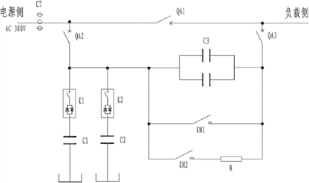
[0027] see figure 1 , the present invention includes a series compensation module and a parallel compensation module connected in parallel between the power supply and the load, the series compensation module and the parallel compensation module are connected in series, the parallel compensation module is arranged on the power supply side, the series compensation module is arranged on the load side, and the parallel compensation module is close to One end of the power supply is provided with a second automatic switch QA 2 , the end of the series compensation module close to the load is provided with a third automatic switch QA 3 , there is a first automatic switch QA between the power supply and the load 1 . The series compensation module and the parallel compensation module are connected to a series-parallel coordinated switching controller cap...


PUM


Abstract

The invention discloses a low-voltage control device applied to a low-voltage distribution network and aiming to keep the obvious effect of series compensation voltage regulation and the continuously adjustable output capacity of parallel compensation and to solve a low-voltage problem. The low-voltage control device comprises a series compensation module and a parallel compensation module which are connected in series with each other between a power supply and a load. The series compensation module comprises a series capacitor bank (C3) and a bypass circuit which are connected in parallel. The series capacitor bank (C3) comprises a plurality of series capacitors connected in parallel. The bypass circuit is a two-stage bypass circuit. The parallel compensation module comprises a plurality of parallel capacitors connected in parallel each of which is connected in series with a combination switch. One end of each parallel capacitor is grounded.

Description

technical field [0001] The invention relates to the field of low-voltage control of distribution networks, in particular to a low-voltage control device applied to low-voltage distribution networks. Background technique [0002] Qualified voltage quality is the need of power users for production and life, and it is also an important condition for power supply enterprises to ensure the safe, reliable and economical operation of the power grid. Many distribution stations have problems such as low voltage at the end of the distribution line and failure of user equipment to work normally during the peak power consumption period. If the line is transformed, the project cost is high, the construction period is long, and the workload is large; traditional shunt capacitors are used The voltage adjustment of the compensation device requires a large installed capacity, and the problem of power factor drop and network loss increase is caused by voltage adjustment; in order to achieve t...

Claims


Application Information

Patent Timeline
Patent Type & Authority Applications(China)
IPC IPC(8): H02J3/16
CPCH02J3/16Y02E40/30
Inventor 许靖杨瑾孟魏刚田文林杨洋杨磊王喜刚杨帆
Owner STATE GRID CORP OF CHINA
Learn More