Large-ground-clearance self-propelled plant protection machine with full hydraulic system

A fully hydraulic, plant protection machine technology, applied in the fields of trapping or killing insects, applications, animal husbandry, etc., can solve the problems of single low-stalk crop application, difficult to meet the application operation, vibration and noise, etc. , to achieve the effect of adjustable ground clearance, reasonable structure and good steering performance

Inactive Publication Date: 2017-06-30
YANSHAN UNIV
10 Cites 0 Cited by

AI-Extracted Technical Summary

Problems solved by technology

[0002] As an important part of agricultural production, self-propelled plant protection machines have received more and more attention in my country. Although my country has carried out some research and development on high-ground gap sprayers, the main models are still difficult to meet the needs of high-stalk crops in the later stages of growth. In complex terrain operat...

Abstract

A large-ground-clearance self-propelled plant protection machine with a full hydraulic system comprises a cab, a pesticide tank, a prime motor system, the hydraulic system, a spraying frame assembly and a chassis structure system, wherein the cab is fixedly arranged at one end of a chassis, the pesticide tank is fixedly arranged in the middle of the chassis, and the spraying frame assembly is arranged at the other end of the chassis. A width-variable drive hydraulic cylinder is arranged on a wheel frame, walking hydraulic motors are arranged on wheels, height-variable drive hydraulic cylinders are vertically arranged at four corners of the wheel frame, hydraulic cycloid motors and slewing bearings are arranged at the lower ends of the height-variable drive hydraulic cylinders, and energy accumulator valve groups are arranged at the upper portions. The large-ground-clearance self-propelled plant protection machine has the advantages of being reasonable in structure, good in steering performance, adjustable in ground clearance and good in stability performance and making spray rods and spray frames convenient to lift and fold, can adapt to low-stem crops and can also adapt to high-stem crops. In addition, a machine body can be automatically kept horizontal, the stability and comfort are higher, meanwhile the machine can smoothly turn in narrow places and is higher in flexibility.

Application Domain

Insect catchers and killers

Technology Topic

Agricultural engineeringSlewing bearing +7

Image

  • Large-ground-clearance self-propelled plant protection machine with full hydraulic system
  • Large-ground-clearance self-propelled plant protection machine with full hydraulic system
  • Large-ground-clearance self-propelled plant protection machine with full hydraulic system

Examples

  • Experimental program(1)

Example Embodiment

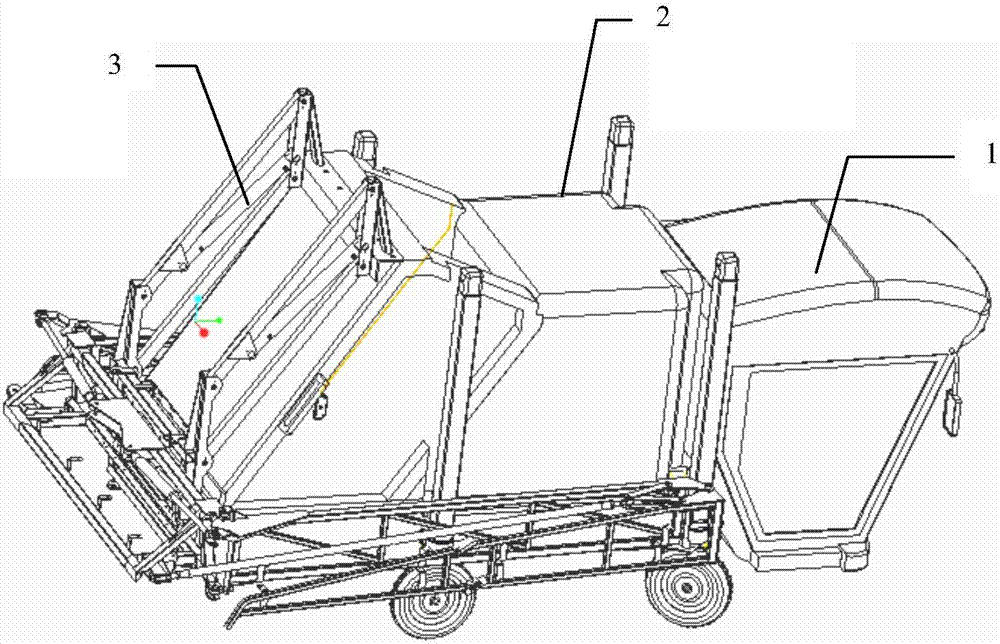
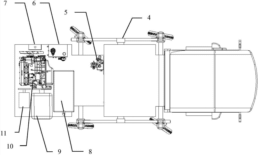
[0018] exist figure 1 and figure 2 In the schematic diagram of the full hydraulic system high ground clearance self-propelled plant protection machine shown, the cab 1 is fixed at one end of the chassis, the medicine box 2 is fixed at the middle of the chassis, and the spray rack assembly 3 is set at the other end of the chassis; the chassis is connected On the wheel frame, the two longitudinal frames in the direction from the cab to the spray rack assembly are square steel, and the two transverse frames connecting the two longitudinal frames are both steel pipes that are divided into two sections, and the steel pipes are covered with sliding sleeves , There is also an intermediate sliding sleeve between the two sliding sleeves. Two width variable driving hydraulic cylinders are arranged in the intermediate sliding sleeve to form a width variable driving mechanism 4. One end of the two width variable driving hydraulic cylinders is connected to the The other ends of the sliding sleeves are respectively fixed on the above-mentioned longitudinal frame, the three sliding sleeves are connected by square steel, and the four corners of the wheel frame are fixed on the outer sliding sleeves of the four height variable driving hydraulic cylinders 12; image 3 and Figure 4 As shown, the wheel 15 is arranged on the four corners under the wheel frame, and the center of the four wheels is provided with a traveling hydraulic motor 16, the slewing bearing 17 is connected with the fixing bracket of the traveling hydraulic motor, and the hydraulic cycloidal motor 13 is connected to the slewing bearing through keys and bolts. The worm is connected with each other to drive the steering. The height variable driving hydraulic cylinder is vertically connected with the hydraulic cycloid motor. The two ends of each height variable driving hydraulic cylinder are respectively connected with the inner and outer sliding sleeves, and each height variable driving hydraulic cylinder. The upper part of the sleeve is provided with an accumulator valve group 14, which is used to automatically balance and keep the chassis level; the engine 10 is fixed on the chassis, the water tank 7 is fixed on the chassis on one side of the engine, and the diesel fuel tank 8 is fixed on the other side of the engine. On the chassis; the hydraulic pump 9 is connected to the engine through gears, the hydraulic control valve 5 is fixed on the medicine box, the hydraulic oil tank 6 is fixed on the chassis next to the water tank, and all the components of the hydraulic system are connected by pipes; the spray rack is fixed on the chassis, The diaphragm pump 11 is arranged on the chassis in the installation frame, and is connected with the engine through gears. The diaphragm pump is connected with the spray frame through pipes. The spray frame lifting device 20 is fixed on the spray frame, and is connected with the hydraulic cylinder through the four-bar linkage mechanism 19 to realize lifting and lowering. , Between the spray lifting device and the large spread arm 21, the expansion is controlled through the connection of the lifting hydraulic cylinder 22. The expansion hydraulic cylinder 23 is also provided on the large spread arm, and the expansion hydraulic cylinder is connected with the small spread arm 18 through a link mechanism. Figure 5 shown.

PUM

no PUM

Description & Claims & Application Information

We can also present the details of the Description, Claims and Application information to help users get a comprehensive understanding of the technical details of the patent, such as background art, summary of invention, brief description of drawings, description of embodiments, and other original content. On the other hand, users can also determine the specific scope of protection of the technology through the list of claims; as well as understand the changes in the life cycle of the technology with the presentation of the patent timeline. Login to view more.

Similar technology patents

Roads traffic collision early warning device

ActiveCN101178846AReasonable structureGood warning effect
Owner:杭州尊鹏信息科技有限公司

Double-mould turnover casting machine for casting piston

Owner:SHIJIAZHUANG JINGANG KAIYUAN POWER SCI & TECH

Polishing device for dustless building grounds

Owner:CHANGSHA WUDAO IND DESIGN CO LTD

Classification and recommendation of technical efficacy words

Why Eureka
Try Eureka