
Liquid control valve apparatus used for micro-fluidic chip and micro-fluidic chip thereof

A microfluidic chip and valve device technology, which is applied to valve devices, measuring devices, laboratory containers, etc., can solve the problems of low stability, single function, and inability to achieve large-scale production, and achieves simple structure, Easy to produce effects

Active Publication Date: 2017-06-30
NANJING LANSION BIOTECH CO LTD
View PDF5 Cites 22 Cited by
  • Summary
  • Abstract
  • Description
  • Claims
  • Application Information

AI Technical Summary

Problems solved by technology

[0010] The existing microfluidic chip valve device has a single function and low stability, and can only prevent the liquid from moving when it is closed.
[0011] Some valves have too high requirements for the combination precision of the upper and lower microfluidic chips, and cannot achieve mass production. A slight change in size will cause the liquid valve to fail, which cannot prevent the flow of liquid.
[0012] Or some valves are used once and cannot be operated repeatedly. For complex microfluidic operations, disposable valves will lead to complicated microfluidic flow channel design and larger volume
Cannot achieve the delicate and stable purpose of POCT

Method used


Image

  • Liquid control valve apparatus used for micro-fluidic chip and micro-fluidic chip thereof
  • Liquid control valve apparatus used for micro-fluidic chip and micro-fluidic chip thereof
  • Liquid control valve apparatus used for micro-fluidic chip and micro-fluidic chip thereof

Examples


Embodiment Construction

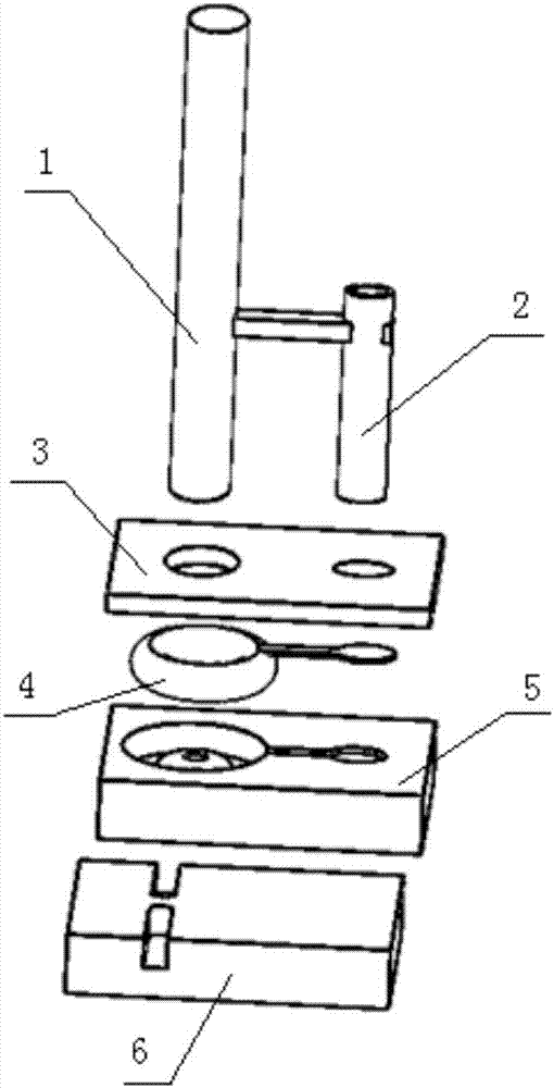
[0039] The following will clearly and completely describe the technical solutions in the embodiments of the present invention with reference to the accompanying drawings in the embodiments of the present invention. Obviously, the described embodiments are only some, not all, embodiments of the present invention. The following description of at least one exemplary embodiment is merely illustrative in nature and in no way taken as limiting the invention, its application or uses. Based on the embodiments of the present invention, all other embodiments obtained by persons of ordinary skill in the art without creative efforts fall within the protection scope of the present invention. The relative arrangements, expressions and numerical values ​​of components and steps set forth in these embodiments do not limit the scope of the present invention unless specifically stated otherwise. At the same time, it should be understood that, for the convenience of description, the sizes of the...


PUM


Abstract

The invention discloses a liquid control valve apparatus used for a micro-fluidic chip and the micro-fluidic chip thereof. The valve apparatus comprises a detection mechanism used for sensing whether the liquid flows through an installation position of the valve apparatus; the feedback value from the detection mechanism shows that the liquid flows through the installation position of the valve apparatus, the valve apparatus in a normally-opened state in the micro-fluidic chip is capable of automatically closing and is in a cut-off state; the valve apparatus in the cutoff state is capable of timely opening and is in a circulation state; the fluid can be circulated in valve apparatus which is in the circulation state under promotion of air flow provided by air passage. The valve apparatus can switch the valve at any time, and can guarantee requirement of large scale production.

Description

technical field [0001] The invention relates to a valve device, in particular to a liquid control valve device for a microfluidic chip. [0002] The invention also relates to a microfluidic chip. Background technique [0003] Immunolateral flow-through diagnostic technology is a stable and practical technology suitable for use in various point-of-care tests (POCT) or on-site. [0004] In the immune system response system, the CV is large due to system reasons, and accurate quantification cannot be achieved. The immunodiagnostic method based on microfluidic technology can effectively avoid the above problems. [0005] There are two types of microfluidics: passive and active. Passive microfluidics still requires capillary force to achieve liquid-forward lateral flow. However, due to the different viscosities of different samples, especially whole blood samples, the liquid flow rate cannot be uniform. [0006] Active microfluidics can effectively avoid the above problems, ...

Claims


Application Information

Patent Timeline
IPC IPC(8): B01L3/00F16K37/00G01N33/558
CPCB01L3/00F16K37/005G01N33/558
Inventor 王龙孙威严万其露
Owner NANJING LANSION BIOTECH CO LTD
Learn More