A Hydrodynamic Cavitation Generator Combined Treatment of Organic Pollutants

A technology of organic pollutants and generators, applied in the research field of sewage cavitation treatment equipment, to achieve the effect of expanding the radiation range, simple structure design, and low energy consumption

Active Publication Date: 2020-10-16
SHAANXI NORMAL UNIV
View PDF6 Cites 0 Cited by
  • Summary
  • Abstract
  • Description
  • Claims
  • Application Information

AI Technical Summary

Problems solved by technology

[0004] In order to overcome the deficiencies in the existing cavitation technology for treating organic pollutants, the present invention provides a combination of perforated plates and reed whistles to fully utilize the sound energy generated by the vibration of the reed whistle, which can increase the radiation range of sound energy, A hydraulic cavitation generator that improves the cavitation effect and strengthens the concentration of free radicals, thereby improving the degradation ability of organic pollutants

Method used


Image

  • A Hydrodynamic Cavitation Generator Combined Treatment of Organic Pollutants
  • A Hydrodynamic Cavitation Generator Combined Treatment of Organic Pollutants
  • A Hydrodynamic Cavitation Generator Combined Treatment of Organic Pollutants

Examples


Embodiment 1

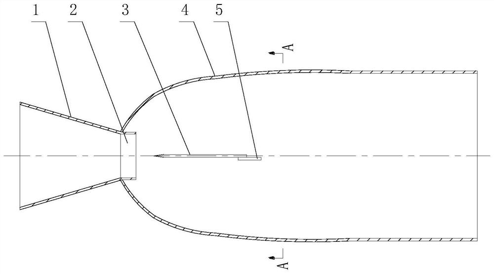
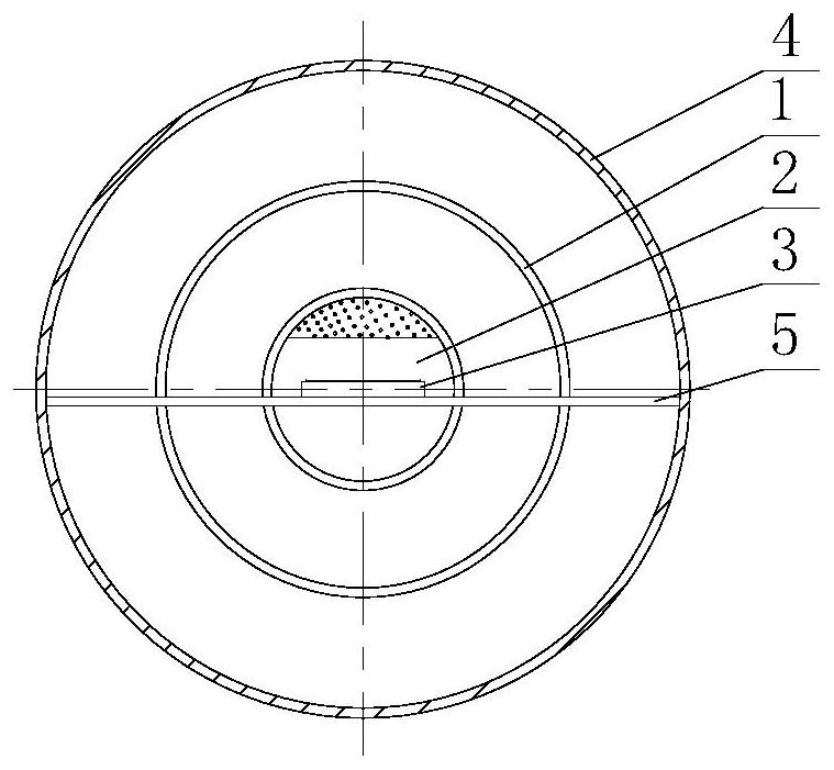
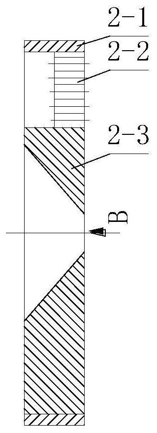
[0036] Depend on figure 1 with 2 It can be seen that the combined hydraulic cavitation generator for treating organic pollutants in this embodiment includes a water inlet pipe 1 , a combined cavitation head 2 , a reed 3 , a cavitation pipe 4 and a fixed plate 5 . Wherein, the inlet end of the water inlet pipe 1 communicates with the water inlet pump, the inner diameter of the inlet end is 60 mm, and the inner diameter of the outlet end is 48 mm. A cavitation pipe 4 is connected to the outlet end of the water inlet pipe 1, and a combined cavitation head 2 is installed at the junction of the water inlet pipe 1 and the cavitation pipe 4. The combined cavitation head 2 is composed of a cavitation sleeve 2-1, The perforated plate 2-2 is composed of the nozzle 2-3, the nozzle 2-3 and the perforated plate 2-2 are installed side by side in the inner cavity of the cavitation sleeve 2-1, and the cavitation sleeve 2-1 is welded to the outlet end of the water inlet pipe 1, It is connect...

Embodiment 2

[0046] Depend on Image 6 with 7 It can be seen that, in this embodiment, the inner diameter of the inlet end of the water inlet pipe 1 is 60 mm, and the inner diameter of the outlet end is 48 mm. A cavitation pipe 4 is connected to the outlet end of the water inlet pipe 1, and a combined cavitation head 2 is installed at the junction of the water inlet pipe 1 and the cavitation pipe 4. The combined cavitation head 2 is composed of a cavitation sleeve 2-1, The perforated plate 2-2 is composed of the nozzle 2-3, the nozzle 2-3 and the perforated plate 2-2 are installed side by side in the inner cavity of the cavitation sleeve 2-1, and the cavitation sleeve 2-1 is welded to the outlet end of the water inlet pipe 1, It is connected with the water inlet pipe 1 as a whole, and a perforated plate 2-2 and a nozzle 2-3 are installed side by side in the inner cavity of the cavitation sleeve 2-1, that is, the perforated plate 2-2 is a semicircular structure, occupying the space of the ...

Embodiment 3

[0057] Depend on Figure 8 with 9 It can be seen that, in this embodiment, the inner diameter of the inlet end of the water inlet pipe 1 is 60 mm, and the inner diameter of the outlet end is 48 mm. A cavitation pipe 4 is connected to the outlet end of the water inlet pipe 1, and a combined cavitation head 2 is installed at the junction of the water inlet pipe 1 and the cavitation pipe 4. The combined cavitation head 2 is composed of a cavitation sleeve 2-1, The perforated plate 2-2 is composed of the nozzle 2-3, the nozzle 2-3 and the perforated plate 2-2 are installed side by side in the inner cavity of the cavitation sleeve 2-1, and the cavitation sleeve 2-1 is welded to the outlet end of the water inlet pipe 1, It is connected with the water inlet pipe 1 as a whole, and a perforated plate 2-2 and a nozzle 2-3 are installed side by side in the inner cavity of the cavitation sleeve 2-1, that is, the perforated plate 2-2 is a semicircular structure, occupying the space of the...


PUM

PropertyMeasurementUnit
thicknessaaaaaaaaaa
angleaaaaaaaaaa
radiusaaaaaaaaaa

Abstract

The invention relates to a hydraulic cavitation generator for combined treatment of organic pollutants. The hydraulic cavitation generator comprises a water inlet pipe and a cavitation pipe communicated with the water inlet pipe; the outlet of the water inlet pipe is convergent, and a combined cavitation head is arranged at the connection of the water inlet pipe and the cavitation pipe; the combined cavitation head is formed by splicing a perforated plate and a nozzle and the center line of the nozzle is coincided with the central axis of the inlet pipe; a reed is arranged in a cavity of the cavitation pipe, and a wedge film of the reed is opposite to the nozzle outlet. The perforated plate is combined with the reed whistle, and the reed is placed in the focus position of the cavitation cavity. When water from the nozzle outlet impacts the reed, the vibration produces sound waves. Sound waves are emitted from the focal position of the cavitation cavity and the sound waves are reflected by the cavitation hook surface of the conical variable section and will be emitted parallel to the direction of the flow, so the radiant range of a loud noise is expanded, cavitation bubbles in the wider area can be effectively cavitated under the effect of sound energy, and the collapse degree of the cavitation bubbles will be further enhanced, so as to improve the degradation ability of organic pollutants.

Description

technical field [0001] The invention belongs to the technical field of sewage cavitation treatment equipment research, in particular to a hydraulic cavitation generator for combined treatment of organic pollutants. Background technique [0002] Water is the material basis for human survival and development, and the protection and recycling of water resources is one of the most important issues in environmental protection. China is one of the thirteen water-poor countries in the world. In the past two decades, my country's water bodies have been seriously polluted. The water bodies surveyed in 118 large and medium-sized cities show that 40% of them are heavily polluted. The main sources of water pollution are industrial polluted wastewater, agricultural polluted wastewater and urban domestic sewage. Especially the "three causes" (carcinogenic, teratogenic, and mutagenic) organic pollutants that are difficult to degrade, they not only consume a large amount of dissolved oxyge...

Claims


Application Information

Patent Timeline
Patent Type & Authority Patents(China)
IPC IPC(8): C02F1/34C02F1/00C02F101/30
CPCC02F1/00C02F1/34C02F2101/30C02F2201/002
Inventor 沈壮志
Owner SHAANXI NORMAL UNIV
Why Eureka
Try Eureka